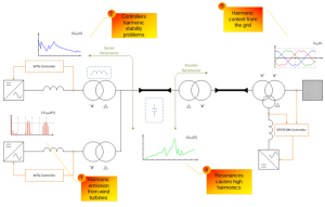
Harmonic emission is recognized as a power quality concern for modern variable-speed wind turbines. For this reason, relevant standards (e.g. IEC 61400-21) require the measurement of harmonics and their inclusion in the power quality certificates of wind turbines. Understanding the harmonic behavior of wind turbines is essential in order to analyze their effect on a grid to which they are connected. Wind turbines with power electronic converters are potential sources of harmonic distortion, and therefore knowledge of their harmonic current emissions is needed to predict wind farm behavior and to design reliable wind farms [1]. The emission of harmonic currents during the continuous operation in steady state of a wind turbine with a power electronic converter must be stated according to the standards.
Nowadays there is a lack of appropriate wind turbine model descriptions for harmonic analysis purposes in standards. It is shown in this paper how the harmonic model should be developed based on measurements. It is recommended to develop wind turbine harmonic models based on the Thevenin (equivalently Norton) approach. The best way is also to compare results with simulations however various aggregation techniques can change measurement results and this should be taken into consideration.
In model development the most crucial measurements are done at the grid-side converter AC terminals and after the main reactor. Based on these measurements the wind turbine harmonic model can be developed based on the Thevenin approach. Please note that the Thevenin approach is equal to the Norton approach in harmonic assessment in wind power plants. The model developed based on the measurements describes the wind turbine harmonic behavior.
In model development it is important to use measurements that can describe the grid-side converter harmonic behavior. The reactor current is the most reasonable choice as well as the voltage at the converter AC terminals or the voltage after the series reactor. Unfortunately both measurement places can introduce some uncertainties.
If one would like to develop the model based on measurements after the series reactor the reactor impedance should be included in the Thevenin impedance. Unfortunately it is not so easy (especially for lower frequencies) to measure the frequency dependent impedance of the reactor. Small errors/uncertainties in the reactor measurements can introduce significant errors in model development, especially for harmonics with low magnitude. Therefore measurements at the grid-side converter AC terminals seem to be more reasonable because the reactor impedance is not needed in the Thevenin impedance. In case of measurements directly at the converter terminals only the internal converter impedance specified by the control structure is required. However such measurements also introduce some uncertainties. Please note that in high power density wind turbines with LV converters there is a need to use several parallel connected converters with sharing reactors. Such converters introduce a certain degree of unbalance which can affect internal harmonic current flow between converter modules. Even if coupled sharing reactors are designed to limit the current imbalance some asymmetry in harmonic generation between converter modules can be seen. The current flowing from the converter to the grid can be assessed based on measurements of all converter modules.
As it was mentioned earlier the converter internal impedance is strongly dependent on control structures applied by different manufacturers. Most of nowadays wind turbines are based on fast current control loop which has the most significant impact on the converter frequency response. Even if in theory the fundamental frequency controller is represented in the same way in natural/stationary reference frame still the controller transfer function may significantly vary if the current control is implemented in stationary or synchronous reference frame [4]. Please note that also harmonic compensation and switching frequency can affect the internal converter impedance. Therefore the internal impedance is kept as a trading secret by the wind turbine and converter units manufacturers.
The problems mentioned above cannot be avoided. Therefore it is recommended to perform simultaneous measurements in both locations (i.e. converter AC terminals and between the series reactor and the wind turbine transformer) and develop two independent models based on two datasets. Later the models can be compared.
In order to avoid any aggregation errors during the calculation of the Thevenin equivalent harmonic voltage sources it is recommended to apply harmonics directly from the Fourier decomposition (i.e. from the 10-cycle window). Later the obtained results (i.e. Thevenin equivalent harmonic sources) could be aggregated according to the methods recommended above. According to IEC 61400-21 there is a need to have at least nine 10min time-series of instantaneous measurements for each power bin. Based on experience it can be said that one month of measurements should be absolutely enough.
At the end it is worth to emphasize the the harmonic assessment approach presented in the IEC 61400-21 standard concerning measurements and power quality assessment in wind turbines assumes measurements of 10-minute harmonic current generated by a wind turbine for frequencies up to 50 times the fundamental frequency of the grid [2], [3]. It has to be emphasized that the most popular standard concerning measurements and power quality assessment of grid-connected wind turbines refers only to current harmonic components without any phase information. Therefore it impossible to evaluate if the harmonic current is flowing into the wind turbine and is mainly caused by background distortions or is caused by the grid-side converter and is flowing from the wind turbine to the grid.
Sometimes based on the power quality report from IEC 61400-21 the wind turbine is modeled as an ideal current source which can cause significant errors in harmonic analysis of wind farms. The harmonic source can be modeled only as an ideal current source for component where the internal converter impedance is equal to infinity. This can happen only for controlled frequencies (e.g. harmonic compensation) and the current value is equal to the reference signal in the control loop [4], [5].
[1] "Wind Turbine Generator Systems – Measurement and Assessment of Power Quality Characteristics of Grid Connected Wind Turbines," IEC 61400-21, 2008.
[2] H. Emanuel, M. Schellschmidt, S. Wachtel, and S. Adloff, "Power quality measurements of wind energy converters with full-scale converter according to IEC 61400-21," in International Conference on Electrical Power Quality and Utilisation, Lodz, 2009, pp. 1-7.
[3] A. Morales, X. Robe, and M. J. C, "Assessment of Wind Power Quality: Implementation of IEC61400-21 Procedures," in International Conference on Renewable Energy and Power Quality, Zaragoza, 2005, pp. 1-7.
[4] Ł. H. Kocewiak, J. Hjerrild, and C. Leth Bak, "Wind Turbine Control Impact on Stability of Wind Farms Based on Real-Life Systems Analysis," in Proc. EWEA 2012 - Europe's Primier Wind Energy Event, Copenhagen, 16-19 April 2012, pp. 1-8.
[5] Ł. H. Kocewiak, "Harmonics in large offshore wind farms," PhD Thesis, 2012, pp. 332, 978-87-92846-04-4.

