Categories
Stability

Converter-based benchmark system from CIGRE 928 technical brochure

Introduction

A small-scale model of an actual AC cable-connected offshore wind power plant (PP) is proposed to compare different stability analysis methods and strategies for mitigating instability in converter-based power systems. This post provides a more detailed description of the benchmark system proposed by CIGRE WG C4.49. The system features power generation units (PGUs) connected to an AC grid via an extensive offshore 66-kV array cable system, offshore step-up transformers, both offshore and onshore HVAC transmission cables, and an onshore step-up transformer.

The primary goal of this benchmark power system is to offer a reference model where interactions between converters, as well as between converters and the grid, can be studied. It is designed to support small-scale, easy-to-model system studies and serve as a foundation for evaluating various instability mitigation methods introduced in CIGRE 928 technical brochure.

The benchmark system includes either aggregated converters or a collection of individual converters linked by a complex MV cable network. The model is formulated in the dq-reference frame to facilitate stability analysis using both impedance and modal approaches, allowing for a direct comparison of their results.

Study cases

Case 1: Aggregated grid following converters connected to a Thevenin equivalent

The transmission system is modeled as a long HVAC cable connected to a simplified Thevenin grid equivalent. The 420 MW power plant is represented by two aggregated power generation units (PGUs) of 180 MW and 240 MW.

The parameters for this aggregated system were derived from a detailed system representation, ensuring that the dynamics of the converters and their interaction with the grid remain consistent between the two. While the original benchmark configuration falls well within the capabilities of the modal and impedance analysis techniques discussed in CIGRE technical brochure 928, a simplified reduced-order model was developed to make the benchmark more accessible for researchers exploring new stability analysis methods, as well as to present results more concisely and clearly.

In this reduced version, each group of 5 PGUs, totaling 20 or 15 PGUs per group, is simplified into an equivalent cable segment and a single PGU. While the reduced model aligns well with the detailed model in the low-frequency range, significant deviations appear at higher frequencies, particularly beyond 500 Hz, as the Nyquist frequency of 1475 Hz, associated with the PGU control system, is approached. Consequently, the reduced-order model is not recommended for studying high-frequency resonance phenomena, but it is suitable for analyzing control interactions in the lower frequency range.

Case 2: Aggregated grid forming converters connected to a Thevenin equivalent

The transmission system is modeled as a long HVAC cable connected to a simplified Thévenin grid equivalent. The 420 MW power plant is represented by two aggregated power generation units of 180 MW and 240 MW. In this scenario, the converters operate in grid-forming control mode.

Download benchmark system

In Matlab

In PSCAD

In PowerFactory

To be ready soon...

References

[1] Ł. Kocewiak, Ch. Buchhagen, R. Blasco-gimenez, J. B. Kwon, M. Larsson, Y. Sun, X. Wang et al., “Multi-frequency stability of converter-based modern power systems,” Technical Brochure 928, Page(s) 1-147, CIGRE, March 2024.
[2] Ł. Kocewiak, R. Blasco-Gimenez, C. Buchhagen, J. B. Kwon, M. Larsson, Y. Sun, X. Wang, “Practical Aspects of Small-signal Stability Analysis and Instability Mitigation,” in Proc. The 21st Wind & Solar Integration Workshop, 12-14 October 2022, The Hauge, The Netherlands.

Categories
Measurements

PhD Course on  Harmonics in Power Electronics and Power Systems

Description:
This course provides a broad overview of power system harmonic problems, methods of analyzing, measuring and effectively mitigating them. Several extended simulation and data processing tools, among others DIgSILENT PowerFactory, Matlab/Simulink or LabVIEW are used to assess and study the harmonic distortion at different points of power networks.
The results of analytical investigation and simulations are validated against measurements applying sophisticated data processing techniques. Furthermore, deep understanding of hardware considerations regarding har- monic measurements in harsh industrial environment is given, using specialized equipment, for in- stance GPS-synchronized measuring instruments.

The course covers the following topics:

  • Power Quality definitions. Generation mechanism of power system harmonics. Harmonic indices.
  • Voltage vs. current distortion as well as parallel vs. series resonance in modern power systems. Point of Common Coupling (PCC).
  • Sources and effects of harmonic distortion.
  • Harmonic measuring instruments and measuring procedures in LV, MV and HV networks.
  • Mathematical tools and theories for analyzing distorted waveforms. Signal processing and uncertainty analysis.
  • Modelling of classical power system components. Harmonic analysis.
  • Modelling of grid-connected converters for harmonic analysis purposes and their application in modern power systems including e.g. offshore wind power plants.
  • Harmonic load-flow, frequency scan and time domain simulations. Linear and nonlinear analysis techniques.
  • Steady-state harmonics vs. harmonic stability. Small-signal representation, sequence and frequency coupling.
  • Software tools for harmonic analysis.
  • Precautionary (preventive) and corrective (remedial) harmonic mitigation techniques. Passive and active line filters. Filter design.

Organizer: Professor Claus Leth Bak
Lecturers: Christian Frank Flytkjær from Energinet and Łukasz H. Kocewiak from Ørsted

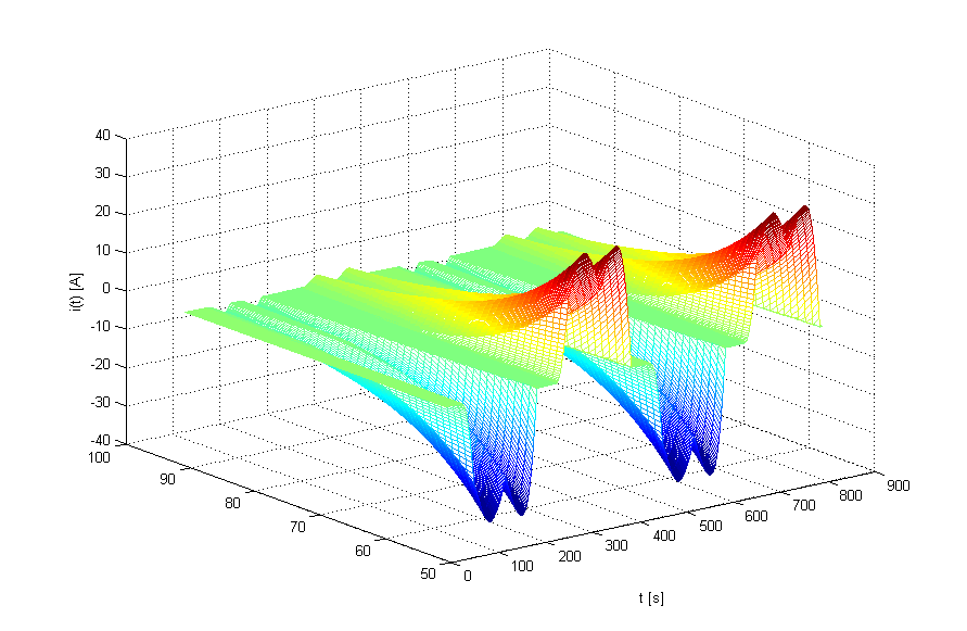
Harmonic current of 6-pulse rectifier supplying a resistive load
Figure 1 Harmonic current of 6-pulse rectifier supplying a resistive load.
Categories
Harmonics Wind Farms

Why do we need a standardized wind turbine harmonic model?

There is clear need from  various wind power industry shareholders such as transmission system operators (TSOs) and distribution network operators (DNOs), wind power plant (WPP) developers, wind turbine (WT) manufacturers, WT component suppliers, academic units, research institutions, certifying bodies and standardization groups (e.g. TC88 MT21) for having a standardized WT harmonic model.

The standard approach in representing a harmonic model would find a broad application in many areas of electrical engineering related to design, analysis, and optimization of WPP electrical infrastructure. Among others this could be evaluation of the WT harmonic performance, system-level harmonic studies, electrical infrastructure design and proposal of harmonic mitigation measures [1].

This starts to be even more important in such multi stakeholder systems as large offshore WPPs where TSOs, offshore transmission owners, component or sub-plant suppliers, WPP developers and operators as well as WT manufacturers need to have a common understanding about harmonic modelling of WTs and harmonic studies in WPPs. This is in relation of harmonic propagation and also harmonic small-signal stability studies.

A standardized approach of WT harmonic model representation is being addressed within IEC TC88 MT21 which will lead to release of IEC TR 61400-21-3 [2]. The structure of the harmonic model presented in the TR will find an application in the following potential areas:

  • Evaluation of the WT harmonic performance during the design of electrical infrastructure and grid code compliance studies.
  • Harmonic studies/analysis of modern power systems incorporating a number of grid-tied converters.
  • Harmonic mitigation measure design by means of active or passive harmonic filtering to optimize electrical infrastructure as well as meet requirements in various grid codes.
  • Sizing of electrical components (e.g. harmonic losses, static reactive power compensation, noise emission, harmonic compatibility levels, etc.) within WPP electrical infrastructure.
  • WPP electrical infrastructure optimization on a system level, e.g. impedance/resonance characteristic shaping, planning levels definition and evaluation etc.
  • Evaluation of external network background distortion impact on WT harmonic assessment as also addressed in IEC 61400-21-1 Annex D.
  • Standardized communication interfaces in relation to WT harmonic data exchange between different stakeholders (e.g. system operators, generators, developers, etc.).
  • Universal interface for harmonic propagation (and possibly stability) studies for engineering software developers.
  • Possible benchmark of WT introduced to the academia and the industry.

The advantage of having standardized WT harmonic performance measure by means of the harmonic model is getting more and more crucial in case of large systems with different types of WT connected to them, e.g. multi-cluster WPPs incorporating different types of WT connected to the same offshore or onshore substation.

[1] Ł. H. Kocewiak, C. Álvarez, P. Muszynski, J. Cassoli, L. Shuai, “Wind Turbine Harmonic Model and Its Application – Overview, Status and Outline of the New IEC Technical Report,” in Proc. The 14th International Workshop on Large-Scale Integration of Wind Power into Power Systems as well as Transmission Networks for Offshore Wind Farms, Energynautics GmbH, 20-22 October 2015, Brussels, Belgium.

[2] IEC TR 61400-21-3:2016 (or 2017), Wind Energy Generation Systems – Part 21-3: Wind turbine harmonic model and its application.

Categories
Harmonics Wind Farms

Wind Turbine Harmonic Model - Some considerations

Nowadays large offshore wind power plants (WPPs) are complex structures including wind turbines (WTs), array cable systems, and HVAC or HVDC offshore/onshore transmission systems. This represents new challenges to the industry in relation to prediction and mitigation of harmonic emission and propagation [1]. Due to increasing complexity of WPPs it is more and more important to appropriately address harmonic analysis of WTs as well as WPP on a system level by means of modelling during the design stage as well as harmonic evaluation during operation.

Harmonic current emissions from the WT are strongly dependent on the WT internal impedances as well as the external network frequency-dependent short circuit impedance. Unfortunately until now there has been no systematic approach to represent a WT from its harmonic performance perspective. This brings inconsistency in WT harmonic performance assessment, evaluation of background distortion in grid-connected WT and harmonic analysis of WPPs.

Due to the different approaches in electrical design taken by WT manufacturers it is convenient to represent WT harmonics in a generic way by means of a Thévenin equivalent circuit comprising an ideal voltage source and an equivalent impedance. Such an equivalent circuit is to be provided for each harmonic component of interest to be included in the model. Therefore using the WT harmonic model, as either Norton or Thévenin equivalent circuits, in simulations with commonly used engineering tools one can estimate the harmonic contribution to the system to which it is connected [2]. WTs as a part of a WPP system can be potentially considered as harmonic sources as well as harmonic mitigation units by means of active and passive filtering thus the structure of the harmonic model should reflect that behavior, e.g. harmonic source and equivalent impedance adjusted accordingly to active filter software settings, equivalent impedance adjustment if the WT passive harmonic filter is incorporated in it.

According to Thévenin's (or Norton’s) theorem any linear electrical network with voltage and current sources and only impedances can be replaced at the terminals of interest by an equivalent voltage source VTh in series connection (or an equivalent current source INo in parallel connection) with an equivalent impedance Zth (or ZNo, where ZTh = ZNo). Thévenin's theorem is dual to Norton's theorem and is widely used for circuit analysis simplification and to study the circuit initial-condition and steady-state response.

Wind Turbine Harmonic Model

[1] Ł. H. Kocewiak, J. Hjerrild, and C. Leth Bak, “Wind Turbine Converter Control Interaction with Complex Wind Farm Systems,” IET Renewable Power Generation, Vol. 7, No. 4, 2013.

[2] Ł. H. Kocewiak, C. Álvarez, P. Muszynski, J. Cassoli, L. Shuai, “Wind Turbine Harmonic Model and Its Application – Overview, Status and Outline of the New IEC Technical Report,” in Proc. The 14th International Workshop on Large-Scale Integration of Wind Power into Power Systems as well as Transmission Networks for Offshore Wind Farms, Energynautics GmbH, 20-22 October 2015, Brussels, Belgium.