Categories
Harmonics Wind Farms

Active filtering vs. passive filtering

Let us think about various sources of harmonic problems in large wind power plants (WPPs) and different ways of optimized harmonic mitigation methods. We discussed previously about harmonic problems such as sources of harmonic emission and amplification as well as harmonic stability which are commonly seen in large WPPs. Fortunately a significant variety of modern preventive and remedial harmonic mitigation methods in terms of passive and active filtering are possible.

Passive filtering

Three-phase harmonic filters utilized in the WPPs nowadays are shunt elements. They are intended to decrease the voltage distortions at the point of interest. From the grid code requirements point of view, a WPP voltage distortion is evaluated at the point of common coupling (PCC).
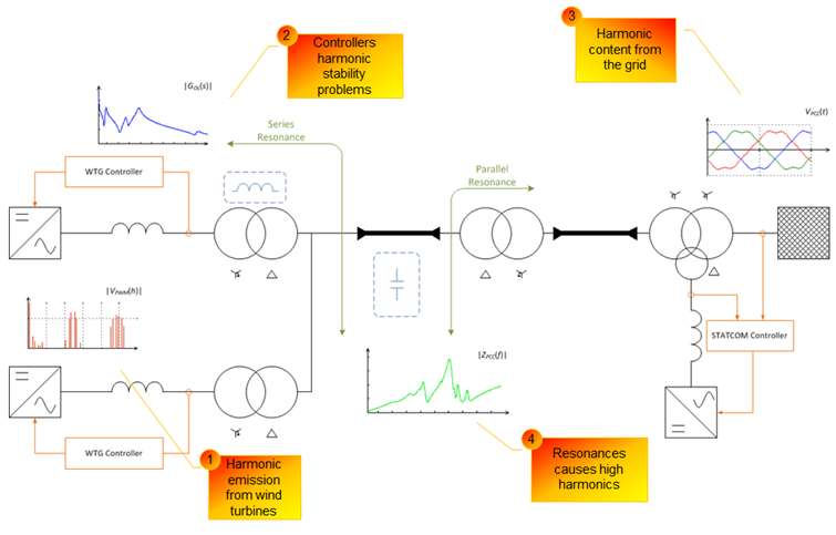
Nonlinear elements such as the power electronic converters, transformers, etc. generate harmonic currents or harmonic voltages inside the WPP as well as in the external network. The resultant harmonic current flows throughout system impedance. Passive harmonic filters reduce distortion by providing low impedance to the harmonic currents.
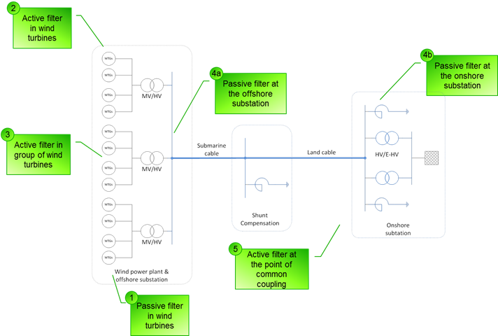
Typical shunt harmonic filters are presented in Fig. 1. Such filtering depending on the harmonic emission source can be installed either in the wind turbine circuit or somewhere at the WPP level (e.g. onshore substation, offshore substation, etc.).

Pros

  • Known state-of-the-art technology,
  • Relatively cheap solution,
  • High reliability due to simplicity in the build,
  • Effective if designed correctly.

Cons

  • Significant size especially for lower frequencies (for large WPPs the tuned frequencies are getting lower),
  • Additional losses,
  • Can cause some over-voltages during switching operations (e.g. energization),
  • Tuned only for specific frequencies (i.e. limited bandwidth),
  • Affected by uncertainties during the WPP design phase,
  • Cannot be easily re-tuned in the case of changing grid conditions during the operation of the WPP,
  • Uncertainties in terms of sizing due to lack of information from wind turbine manufacturers and TSOs during the design phase,
  • Size limitations during design due to e.g. limited space at offshore substation,
  • Long lead-time because of custom-made reactors.

Active filtering

All active filtering solutions employ power electronic converters for the absorption (e.g. harmonic compensation) or suppression (e.g. active damping) of harmonics. Nowadays large WPPs are already equipped with a number of grid connected converters either as a part of the wind turbines or as some sort of FACTS devices. In that case, the implementation of active filtering technique would only mean the retuning of the converter controller in order to meet with controlled harmonic levels.
The converter might be controlled adaptively or otherwise to suppress the selected critical harmonic components. From this perspective there is no need to interfere with the WPP design but it entails to providing additional control features. Such issues could be specified on a contractual level and required to be provided as an add-on together with the product.
Connecting all possible active filtering methods together with state-of-the-art passive filtering methods an optimized hybrid solution can be obtained.

Pros

  • Already existing technologies such as STATCOMS can be utilized for the active filtering at the PCC,
  • Active tuning might be permissible even during the operation,
  • Almost unlimited control potential (e.g. selective harmonic compensation, wide band high-pass active filtering, etc.),
  • Network impedance changes during operation could be addressed,
  • Control method can be tuned for each of WPPs independently taking into consideration grid code issues as well as WPP structure,
  • Negligible losses for series connected active filters such as wind turbines,
  • Reduces risk due to uncertainties related with lack of information from manufacturers (e.g. models) and TSOs (e.g. harmonic background, models, etc.).

Cons

  • Recent technology; not commonly applied in WPPs,
  • May suffer from harmonic stability problems,
  • Improved bandwidth and increased switching frequency is needed,
  • Component sizing issues and limited DC-link voltage utilization.

[1] Ł. H. Kocewiak, "Harmonics in Large Offshore Wind Farms," PhD Thesis, Aalborg University, Aalborg, 2012.
[2] Ł. H. Kocewiak, S. K. Chaudhary, B. Hesselbæk, "Harmonic Mitigation Methods in Large Offshore Wind Power Plants," in Proc. of The 12th International Workshop on Large-Scale Integration of Wind Power into Power Systems as well as Transmission Networks for Offshore Wind Farms, Energynautics GmbH, London, UK, 22-24 October 2013, 443-448.

Categories
Harmonics Wind Farms

Harmonic mitigation methods in wind power plants

There are various techniques for dealing with the harmonic problem in large wind power plants (WPPs) depending upon the nature and source of the problem.
Large offshore WPPs are characterized by complex structures including wide application of power electronic devices in wind turbines, FACTS devices and/or HVDC transmission. Moreover, there is a large amount of passive components such as filters, cable arrays, transformers, transmission cables, and shunt compensation equipment. Consequently, there are many potential sources of harmonic problems, and simultaneously many ways of dealing with them [1].
Primarily there are two methods of harmonic mitigation in a WPP: (i) avoiding harmonic resonance by design and (ii) design and use of filters [2]. A good design involves system layout, component selection and controller tuning with the aim of avoiding potential resonance conditions in the WPP.

Harmonic mitigation methods
Fig. 1 Harmonic mitigation methods in wind power plants.

Both passive and active filtering could be used for harmonic mitigation. It is recognized that passive filtering is the state-of-the-art technology. However, it requires extensive knowledge of the system during the WPP design phase. In many cases information about the system is uncertain and over-sizing of passive filters may take place to cover uncertainties and risks.
Due to the fact that more and more power electronic equipment (e.g. wind turbines with grid connected converter, STATCOMs, HVDC, etc.) is being utilised in WPPs, active filtering appears to be an interesting solution.
Active filtering can be implemented at the converter control level, thereby avoiding or reducing the need for installing expensive passive filters. Moreover, active filter controllers could be tuned and re-tuned, sometimes adaptively, to overcome the uncertainties faced during the WPP design phase [3].
A comparison between passive and active filters including major factors is presented in Table 1. It can be easily seen that there is a potential in active filtering and the technology is improving.

Table 1 Comparison between passive and active filtering technology.

Indices Passive filters Active filters
Technology Known Improving
Reliability High Medium
Effectiveness Medium Good
Engineering time Large Medium
Power electronics No Yes
Energy storage Large Small
EMI No Yes
Control circuit No Yes
Voltage regulation No Yes
Dynamic response Slow Fast
Cost Low High

Considering the different attributes, probably hybrid solutions involving both the passive and the active filters at various locations, as shown in Fig. 1, would be the most beneficial for effective harmonic mitigation scheme. In order to optimize the WPP design from harmonic emission and stability perspective some more studies and research is required [4]. The hybrid solutions would comprise of:

  1. Passive filtering at the wind turbine level:
    • trap filters designed for carrier group harmonics filtering,
    • high-pass filters for high frequency content,
    • detuned C-type filters with limited bandwidth, etc.
  2. Active filtering at the wind turbine level:
    • selective harmonic compensation,
    • high-pass active filtering,
    • harmonic rejection capability,
    • active notch filters, etc.
  3. Active filtering in groups of wind turbines:
    • carrier signals de-synchronization,
    • phase shifter transformer groups, etc.
  4. Passive filtering at the WPP level – 4b) onshore or 4a) offshore:
    • detuned C-type filters,
    • double-tuned filter, etc.
  5. Active filtering at the WPP level:
    • shunt connected FACTS devices,
    • HVDC link, etc.

[1] V. Akhmatov, J. Nygaard Nielsen, J. Thisted, E. Grøndahl, P. Egedal, M. Nørtoft Frydensbjerg, and K. Høj Jensen, "Siemens Wind Power 3.6 MW Wind Turbines for Large Offshore Wind Farms," in Proc. 7th International Workshop on Large Scale Integration of Wind Power and on Transmission Networks for Offshore Wind Farms, 26-27 May 2008, pp. 494-497.
[2] M. Bradt, B. Badrzadeh, E. Camm, D. Mueller, J. Schoene, T. Siebert, T. Smith, M. Starke, and R. Walling, “Harmonics and resonance issues in wind power plants,” 2011 IEEE PES General Meeting, Jul. 2011.
[3] Ł. H. Kocewiak, "Harmonics in Large Offshore Wind Farms," PhD Thesis, Aalborg University, Aalborg, 2012.
[4] P. Brogan, "The stability of multiple, high power, active front end voltage sourced converters when connected to wind farm collector systems," in EPE Wind Energy Chapter Seminar, Stafford, 2010, pp. 1-6.

Categories
Harmonics Wind Farms

Harmonic problems in wind power plants

Harmonics has always been of special concern in power system studies. In the past the power system comprised mainly of passive components with relatively linear operating range and synchronous generators. Harmonic analysis of such systems is the state-of-the art right now.
The wind turbines are nowadays mainly connected together into a collector system through a widespread network of medium voltage (MV) sub-sea cables. The voltage is then stepped up and the wind power plant (WPP) is connected to the power grid through long high voltage (HV) cables which constitute the HVAC or HVDC transmission system. Such configuration is still being challenging to the industry from harmonic generation, propagation and stability perspective [1].
The presence of harmonics inside the WPP is a nuisance as it leads to higher current and voltage levels in the system. Consequently, the system loss is higher system, and there is higher component stress. Moreover, if there is series or parallel resonance points in the WPP, the resonating harmonics may get amplified and then that can be destructive. The resonance can be series or parallel type as shown in Fig. 1. Besides, there are other issues with harmonic interference and power quality [2].

Harmonic problems in wind farms
Fig. 1 Harmonic problems in wind power plants.

Identification of the presence of harmonics in the system and potential resonance conditions are very critical for the design of a WPP. Measurement of harmonic content is an important element of the WPP and wind turbine evaluation process. Measurement of field data is also required to validate the theoretical analysis and numerical simulations. The measurement equipment should be carefully adjusted in order to record harmonics of interest with acceptable accuracy and precision.
The harmonic measurements should be carried out during continuous wind turbine normal operation, i.e. fault free operation complying with the description in the wind turbine manual excluding wind turbine start-up and shutdown as described in IEC 61400-21. Since different operational modes are characterized by different frequency response of the converter thereby affecting the harmonic emission, the operational modes should be considered, and any change in the mode should be noted during the measurement process [3].
It is also recommended to perform measurements when the wind turbines are not operational such that the harmonic background spectrum can be evaluated. The wind turbine during background measurements should neither inject nor absorb any harmonic current during this process.
Harmonic mitigation by design is affected by several uncertainties in different factors during the design of a WPP. Some of them are listed below:

  • Lack of accurate models provided by the manufacturers.
  • Component tolerances in the WPP model.
  • Wind turbine harmonic emission model uncertainties.
  • Phase angle between harmonics from different wind turbines and possible harmonic cancellation.
  • Different operating modes of the wind turbines (e.g. power production levels, wake effects, voltage control, etc.).
  • Lack of reliable information from TSOs and DSOs for the external network model.
  • Changes in the wind turbine converter controller affecting harmonic emission.
  • Linear model of WPP components (e.g. transformers, converters, cables, etc.).
  • Linear harmonic load flow calculation method excluding possible frequency coupling.

[1] Ł. H. Kocewiak, C. L. Bak, J. Hjerrild, "Wind Turbine Converter Control Interaction with Complex Wind Farm Systems," IET Renewable Power Generation, Vol. 7, No. 4, 2013.
[2] Ł. H. Kocewiak, S. K. Chaudhary, B. Hesselbæk, "Harmonic Mitigation Methods in Large Offshore Wind Power Plants," in Proc. of The 12th International Workshop on Large-Scale Integration of Wind Power into Power Systems as well as Transmission Networks for Offshore Wind Farms, Energynautics GmbH, London, UK, 22-24 October 2013, 443-448.
[3] Ł. H. Kocewiak, "Harmonics in Large Offshore Wind Farms," PhD Thesis, Aalborg University, Aalborg, 2012.

Categories
Software

How to adjust figures in Matlab?

I was asked few times about possible adjustment of figures in Matlab. Many times there is simply a need to change slightly the default view in order to align with the template in our publication, book, etc. Thus I will try to show few parameters that can easily adjust the view according to our expectations.

Fortunately in Matlab there is an extended flexibility of doing that. I need to admit that it is much more convenient to edit figures in Matlab than in other engineering tools (e.g. LabVIEW, PSCAD, PowerFactory, etc.). Therefore I personally export all of my results into Matlab and later adjust.

Let me explain how to obtain the following figures. As one can see the figures present the same result but slightly in a different way. I do not need to mention that nicely presented research results can easily attract broader audience. Hence even in the conservative scientific world it is of great importance to be able selling our findings.

Notch Filter - Bode Plot
Notch Filter - 3D Phase

The figures above show the variation of notch filter depending on the quality factor. The filter is tuned for 100Hz and included in synchronous reference frame and afterwards represented in natural/stationary reference frame. Thus the resonant peaks are shifted ±50Hz. The notch filter transfer function is expressed in the following way.

Such figures can be obtained by using the following code. Please note that also Control System Toolbox is needed to obtain the frequency response of the notch filter.

% Prepare workspace
clc, clear('all'), close('all'),
% Define font parameters
fontname= 'Cambria';
set(0,'defaultaxesfontname',fontname);
set(0,'defaulttextfontname',fontname);
fontsize= 10;
set(0,'defaultaxesfontsize',fontsize);
set(0,'defaulttextfontsize',fontsize);
% Get screen resolution
scrsz= get(0,'ScreenSize');

%% Notch filter
% Define frequency parameters
f= 50;                    % Grid frequency [Hz]
omegaO= 2*pi*f;           % Angular frequency [rad/s]
omegaN= 2*omegaO;         % Resonant frequency [rad/s]
step= 0.1;                % Frequency step [Hz]
frequencySeries= 1:step:200;
omegaSeries= 2*pi*frequencySeries;
% Construct transfer function
s= tf('s');
sN= s-1i*omegaO;
sP= s+1i*omegaO;
% Allocate memory
firstIndex= 1; lastIndex= 30; k= 1;
surfTf= zeros(length(frequencySeries),lastIndex);
map= zeros(lastIndex,3);

%% Display results
% Initiate figure
f1= figure('Name','Transfer Function Plot',...
'Position',[scrsz(3)*0.2 scrsz(4)*0.2 scrsz(3)*0.35 scrsz(4)*0.45]);
hold('on'),
for index=firstIndex:k:lastIndex,
     Qn= 100/sqrt(2); Qd= index+5;           % Quality factor
     GnN= (sN^2+omegaN*sN/Qn+omegaN^2)/(sN^2+omegaN*sN/Qd+omegaN^2);
     GnP= (sP^2+omegaN*sP/Qn+omegaN^2)/(sP^2+omegaN*sP/Qd+omegaN^2);
     Gn= 1/2*(GnP+GnN);                      % From SRF to NRF
     [magGn,phaseGn]= bode(Gn,omegaSeries);  % Frequency response
     GnCplx= magGn.*exp(1i*phaseGn);
     surfTf(:,index)= GnCplx(:);
     sub1= subplot(2,1,1,'Parent',f1);box(sub1,'on'),hold(sub1,'all'),
     plot(frequencySeries,abs(GnCplx(:)),...
          'Color',[0 1-index/lastIndex index/lastIndex]),
          ylabel('|{\itG_{notch}}| [abs]'),
          xlim([min(frequencySeries) max(frequencySeries)]),
          ylim([0.5 1.02]),hold('on'),grid('off'),
     sub2= subplot(2,1,2,'Parent',f1);box(sub2,'on'),hold(sub2,'all'),
     plot(frequencySeries,180*unwrap(angle(GnCplx(:)))/pi,...
          'Color',[0 1-index/lastIndex index/lastIndex]),
          xlim([min(frequencySeries) max(frequencySeries)]),
          ylim([-1100 1300]),hold('on'),grid('off'),
          ylabel('\angle{\it{G_{notch}}} [\circ]'),xlabel('{\itf} [Hz]'),
     map(index,:)= [0 1-index/lastIndex index/lastIndex];
end
c1= colorbar('peer',sub1,'East');colormap(map),
set(c1,'YTickMode','manual','YTickLabelMode','manual',...
 'YTick',[firstIndex; floor((lastIndex-firstIndex)/2); lastIndex],...
 'YTickLabel',[firstIndex+5; floor((lastIndex-firstIndex)/2)+5; lastIndex+5]),
hold('off'),

f2= figure('Name','Impedance Angle',...
     'Position',[scrsz(3)*0.2 scrsz(4)*0.2 scrsz(3)*0.35 scrsz(4)*0.45]);
ax2= axes('Parent',f2);grid(ax2,'on'),hold(ax2,'all'),
mesh(180*unwrap(angle(surfTf))/pi),zlabel('\angle{\it{G_{notch}}} [\circ]'),
     ylabel('{\itf} [Hz]'),xlabel('{\itQ_n} ','Rotation',322),view([60 40]),
set(gca,'XTick',[firstIndex; floor((lastIndex-firstIndex)/2); lastIndex],...
 'XTickLabel',[firstIndex+5; floor((lastIndex-firstIndex)/2)+5; lastIndex+5],...
 'YTick',1:50/step:length(frequencySeries),...
 'YTickLabel',min(frequencySeries):50:max(frequencySeries)),

Feel free to use and modify included Matlab code. I am also looking forward to hear from you in case of any suggestions and comments.

Categories
Harmonics

Wind turbine harmonic models

Harmonic emission is recognized as a power quality concern for modern variable-speed wind turbines. For this reason, relevant standards (e.g. IEC 61400-21) require the measurement of harmonics and their inclusion in the power quality certificates of wind turbines. Understanding the harmonic behavior of wind turbines is essential in order to analyze their effect on a grid to which they are connected. Wind turbines with power electronic converters are potential sources of harmonic distortion, and therefore knowledge of their harmonic current emissions is needed to predict wind farm behavior and to design reliable wind farms [1]. The emission of harmonic currents during the continuous operation in steady state of a wind turbine with a power electronic converter must be stated according to the standards.

Nowadays there is a lack of appropriate wind turbine model descriptions for harmonic analysis purposes in standards. It is shown in this paper how the harmonic model should be developed based on measurements. It is recommended to develop wind turbine harmonic models based on the Thevenin (equivalently Norton) approach. The best way is also to compare results with simulations however various aggregation techniques can change measurement results and this should be taken into consideration.

In model development the most crucial measurements are done at the grid-side converter AC terminals and after the main reactor. Based on these measurements the wind turbine harmonic model can be developed based on the Thevenin approach. Please note that the Thevenin approach is equal to the Norton approach in harmonic assessment in wind power plants. The model developed based on the measurements describes the wind turbine harmonic behavior.

In model development it is important to use measurements that can describe the grid-side converter harmonic behavior. The reactor current is the most reasonable choice as well as the voltage at the converter AC terminals or the voltage after the series reactor. Unfortunately both measurement places can introduce some uncertainties.

If one would like to develop the model based on measurements after the series reactor the reactor impedance should be included in the Thevenin impedance. Unfortunately it is not so easy (especially for lower frequencies) to measure the frequency dependent impedance of the reactor. Small errors/uncertainties in the reactor measurements can introduce significant errors in model development, especially for harmonics with low magnitude. Therefore measurements at the grid-side converter AC terminals seem to be more reasonable because the reactor impedance is not needed in the Thevenin impedance. In case of measurements directly at the converter terminals only the internal converter impedance specified by the control structure is required. However such measurements also introduce some uncertainties. Please note that in high power density wind turbines with LV converters there is a need to use several parallel connected converters with sharing reactors. Such converters introduce a certain degree of unbalance which can affect internal harmonic current flow between converter modules. Even if coupled sharing reactors are designed to limit the current imbalance some asymmetry in harmonic generation between converter modules can be seen. The current flowing from the converter to the grid can be assessed based on measurements of all converter modules.

As it was mentioned earlier the converter internal impedance is strongly dependent on control structures applied by different manufacturers. Most of nowadays wind turbines are based on fast current control loop which has the most significant impact on the converter frequency response. Even if in theory the fundamental frequency controller is represented in the same way in natural/stationary reference frame still the controller transfer function may significantly vary if the current control is implemented in stationary or synchronous reference frame [4]. Please note that also harmonic compensation and switching frequency can affect the internal converter impedance. Therefore the internal impedance is kept as a trading secret by the wind turbine and converter units manufacturers.

The problems mentioned above cannot be avoided. Therefore it is recommended to perform simultaneous measurements in both locations (i.e. converter AC terminals and between the series reactor and the wind turbine transformer) and develop two independent models based on two datasets. Later the models can be compared.

In order to avoid any aggregation errors during the calculation of the Thevenin equivalent harmonic voltage sources it is recommended to apply harmonics directly from the Fourier decomposition (i.e. from the 10-cycle window). Later the obtained results (i.e. Thevenin equivalent harmonic sources) could be aggregated according to the methods recommended above. According to IEC 61400-21 there is a need to have at least nine 10min time-series of instantaneous measurements for each power bin. Based on experience it can be said that one month of measurements should be absolutely enough.

At the end it is worth to emphasize the the harmonic assessment approach presented in the IEC 61400-21 standard concerning measurements and power quality assessment in wind turbines assumes measurements of 10-minute harmonic current generated by a wind turbine for frequencies up to 50 times the fundamental frequency of the grid [2], [3]. It has to be emphasized that the most popular standard concerning measurements and power quality assessment of grid-connected wind turbines refers only to current harmonic components without any phase information. Therefore it impossible to evaluate if the harmonic current is flowing into the wind turbine and is mainly caused by background distortions or is caused by the grid-side converter and is flowing from the wind turbine to the grid.

Sometimes based on the power quality report from IEC 61400-21 the wind turbine is modeled as an ideal current source which can cause significant errors in harmonic analysis of wind farms. The harmonic source can be modeled only as an ideal current source for component where the internal converter impedance is equal to infinity. This can happen only for controlled frequencies (e.g. harmonic compensation) and the current value is equal to the reference signal in the control loop [4], [5].

[1] "Wind Turbine Generator Systems – Measurement and Assessment of Power Quality Characteristics of Grid Connected Wind Turbines," IEC 61400-21, 2008.
[2] H. Emanuel, M. Schellschmidt, S. Wachtel, and S. Adloff, "Power quality measurements of wind energy converters with full-scale converter according to IEC 61400-21," in International Conference on Electrical Power Quality and Utilisation, Lodz, 2009, pp. 1-7.
[3] A. Morales, X. Robe, and M. J. C, "Assessment of Wind Power Quality: Implementation of IEC61400-21 Procedures," in International Conference on Renewable Energy and Power Quality, Zaragoza, 2005, pp. 1-7.
[4] Ł. H. Kocewiak, J. Hjerrild, and C. Leth Bak, "Wind Turbine Control Impact on Stability of Wind Farms Based on Real-Life Systems Analysis," in Proc. EWEA 2012 - Europe's Primier Wind Energy Event, Copenhagen, 16-19 April 2012, pp. 1-8.
[5] Ł. H. Kocewiak, "Harmonics in large offshore wind farms," PhD Thesis, 2012, pp. 332, 978-87-92846-04-4.