Categories
Methodology Product Management

Strategic Product Roadmap: 5 Key Functions Every Product Owner Should Know

Most product roadmaps fail because they focus on what will be built, but ignore why it matters and how it will be delivered at scale. A strategic product roadmap fixes this by connecting business outcomes (why) with clear initiatives (what) and the architecture runway and technology direction (how) needed to enable them across the next 3–4 PIs. Instead of acting as a static plan, it becomes a practical decision framework that helps Product Owners align stakeholders, prioritize effectively, and translate strategy into coordinated, executable work that delivers measurable value.

Translate strategy into actionable initiatives

Translating strategy into actionable initiatives is where a roadmap becomes useful for delivery, not just direction. Strategy is often too abstract to execute, so Product Owners must turn it into clearly defined initiatives that teams can understand, plan, and break down into backlog-ready work. This step creates a shared bridge between intent and execution, ensuring that multiple teams move in the same direction instead of solving problems in isolation.

  • From abstract goals to concrete initiatives – Reframe broad objectives (e.g. “improve UX consistency”) into specific initiatives (e.g. “standardize components, unify navigation, define design tokens”).
  • From initiatives to executable work – Decompose initiatives into epics and features that can be directly reflected in team backlogs and planned across PIs.
  • From isolated tasks to coordinated direction – Ensure initiatives are cross-cutting and aligned across products, so teams contribute to shared outcomes rather than fragmented improvements.

Focus: Convert each strategic (direction) goal into roadmap initiatives and break them down into epics (or features) that can be added to the backlog.

Align delivery with business outcomes

Aligning delivery with business outcomes ensures that teams focus on creating measurable value, not just shipping features. A strategic roadmap makes this explicit by linking every initiative to a clear purpose, expected impact, and success metric. This shifts the conversation from “what are we building?” to “what are we achieving?”, helping Product Owners prioritize effectively and avoid low-impact work.

  • From outputs to outcomes – Define the expected result of each initiative (e.g. increased adoption, reduced effort, faster delivery), not just the feature being delivered.
  • Tie work to measurable success – Connect initiatives to concrete KPIs or signals, so progress can be evaluated beyond completion.
  • Prioritize based on impact – Use outcomes to decide what to do first, focusing on initiatives that deliver the highest business value rather than the loudest requests.

Focus: Define one measurable outcome for every roadmap initiative before bringing them to a PI.

Prioritize and sequence work across PIs

Prioritizing and sequencing work across PIs ensures that delivery is focused, realistic, and unblocked, rather than reactive and overloaded. A strategic roadmap helps Product Owners decide not only what is important, but what should happen first, what can wait, and how work should flow over time, balancing business priorities with dependencies and technical readiness. This creates a clear path from strategy to execution while keeping flexibility in later PIs.

  • Prioritize based on value and constraints – Balance business impact, dependencies, and technical feasibility to decide what truly deserves focus in each PI.
  • Sequence for flow, not urgency – Plan work so that foundational elements (e.g. research, architecture runway) come before dependent features, avoiding rework and delays.
  • Keep future PIs adaptable – Define near-term work clearly, but leave later PIs at a higher level to allow learning and adjustment without overcommitting.

Focus: Order roadmap initiatives based on value, dependencies, and technical readiness – and explicitly decide what will not be done now.

Connect strategy to execution and communication

Connecting strategy to execution and communication ensures that everyone – from leadership to delivery teams – is aligned on where the product is going, why it matters, and how work translates into results. A strategic roadmap acts as a shared reference point that links high-level goals with day-to-day activities, while also providing a clear narrative for stakeholders. This reduces misalignment, improves decision-making, and keeps teams focused on delivering meaningful outcomes.

  • Create a shared understanding – Present initiatives in a way that is clear for both business and technical stakeholders, so everyone aligns on priorities and direction.
  • Bridge planning and delivery – Ensure roadmap initiatives are directly connected to epics and backlog items, making strategy actionable for teams.
  • Communicate intent, not just status – Use the roadmap to explain why work is prioritized and what value it will bring, helping manage expectations and build trust.

Focus: Ensure every roadmap initiative is linked to backlog items and can be clearly explained to both stakeholders and teams in one sentence.

Sync with the architecture runway

Synchronizing with the architecture runway ensures that product plans are technically feasible, scalable, and not blocked during delivery, even though Product Owners do not own the architecture itself. While the System Architect defines and evolves the runway, Product Owners must actively connect roadmap initiatives with the required technical capabilities, so that features are delivered on top of a ready foundation rather than being delayed or compromised.

  • Ensure visibility of dependencies – Identify which initiatives depend on specific architectural capabilities (e.g. APIs, design systems, data models) and make these dependencies explicit in the roadmap.
  • Align timing with technical readiness – Coordinate with the System Architect so that the necessary runway elements are planned and delivered before or alongside dependent features.
  • Facilitate continuous collaboration – Maintain regular alignment with architecture stakeholders to validate feasibility, adjust sequencing, and avoid disconnects between product ambition and technical reality.

Focus: For each roadmap initiative, confirm with the architect what technical enablers are required and when they will be ready.

In short

A strategic product roadmap is not just a plan of what will be built, but a coordinated framework that aligns business outcomes, product initiatives, and technical readiness over time. For Product Owners, its role is to ensure that work is driven by value, translated into actionable initiatives, properly prioritized across PIs, clearly connected to execution, and synchronized with the architecture runway owned by System Architects. When used effectively, the roadmap becomes a shared decision-making and communication tool that links strategy to delivery and ensures that what teams build is both meaningful and feasible.

Dictionary

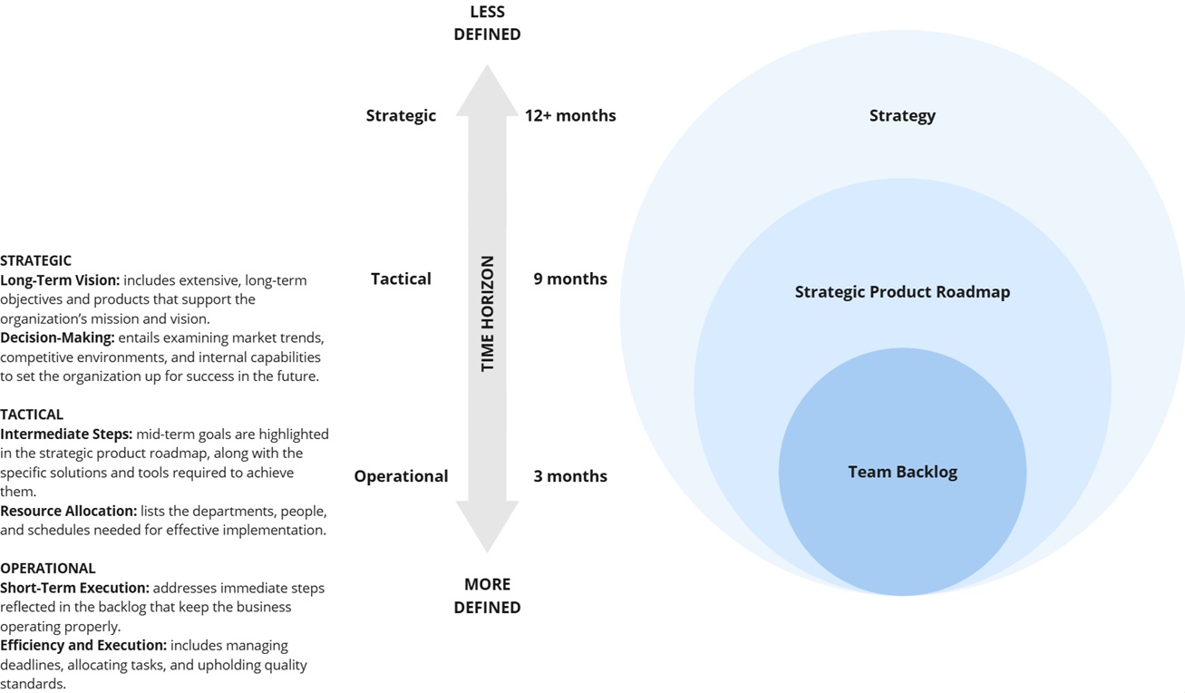
(Strategic) Goal: A desired business outcome the organization wants to achieve.
(Roadmap) Initiative: A high-level investment area that defines how a goal will be pursued.
Epic: A large, value-driven piece of work that delivers a specific capability and can be broken into smaller items.
Feature: A specific functionality or capability that provides value to users or systems.
Story: A small, implementable unit of work describing a user need or system behavior.

LevelFocusBelongs toGranularity
GoalWhy (outcome)StrategyVery high (Long-term)
InitiativeWhat / Why (direction)RoadmapHigh (Multiple PIs)
EpicWhat (deliverable)Backlog (bridge)Medium (Multiple PIs)
FeatureWhat (detailed)BacklogLower (One PI or less)
StoryHow (execution)BacklogVery low (One iteration)

References

[1] C. Todd Lombardo, Bruce McCarthy, Evan Ryan, Michael Connors, “Product Roadmaps Relaunched,” O'Reilly Media, October 2017.
[2] Scaled Agile Framework (SAFe), “Roadmap,” URL: https://framework.scaledagile.com/roadmap/, Last Update: 25 February 2025.
[3] Marty Cagan, “Inspired: How to Create Tech Products Customers Love,” Wiley, 2017.

Categories
Product Management Software

The 6 Phases of Product Lifecycle: Idea, Explore, Validate, Grow, Sustain, Retire

Product Lifecycle Management (PLM) describes how a product evolves from an initial idea to eventual retirement. The lifecycle helps organizations manage uncertainty in early stages while focusing on growth and profitability once a product proves its market fit. Each of 6 phases has a different purpose, timeframe, and success metrics. Early stages (i.e. Idea, Explore, Validate) emphasize learning and experimentation with potential customers, while later stages (e.g. Grow, Sustain, Retire) focus on scaling, operational efficiency, and financial performance. Understanding these phases helps allocate people effectively and manage products throughout their entire lifecycle.

Phases of Product Lifecycle

Idea

The Idea phase is where potential product opportunities are identified. Teams recognize customer problems, unmet needs, or market gaps that could lead to valuable solutions. Ideas may come from customer feedback, technological advances, internal innovation, or strategic business goals. At this stage, concepts are still rough hypotheses rather than defined products. The goal is to quickly assess whether the opportunity is worth exploring further. Activities typically include problem framing, initial discussions, and collecting early insights from users or the market.

Explore

The Explore phase focuses on understanding the problem space and identifying possible solution approaches. Teams conduct research to learn about user needs, behaviors, and market conditions. The objective is to confirm that the problem is real and significant. Activities may include user interviews, market analysis, early concept sketches, and exploratory prototypes. Multiple ideas can be evaluated during this phase. The emphasis is on learning and reducing uncertainty before committing significant development effort.

Validate

The Validate phase tests whether the proposed solution effectively solves the identified problem and creates value for users. Teams develop prototypes or minimum viable products (MVPs) and test them with early adopters. Experiments and usability testing help verify assumptions about desirability, usability, and feasibility. Metrics such as user engagement, activation, and retention are often monitored. The aim is to confirm product–market fit and ensure that the solution is viable before scaling development and investing in broader delivery.

Grow

The Grow phase begins once the product has demonstrated clear value and product–market fit. The focus shifts to increasing adoption and expanding the customer base. Teams improve reliability, performance, and user experience while adding features that strengthen the product’s value proposition. Marketing and distribution efforts intensify to reach a wider audience. Infrastructure and support capabilities are also scaled to accommodate growth. Key indicators during this phase include adoption rates, revenue growth, and customer retention.

Sustain

The Sustain phase represents the maturity of the product. Adoption has stabilized and the product delivers consistent value to customers and the business. Development efforts emphasize incremental improvements, reliability, and operational efficiency rather than major innovation. Teams focus on maintaining competitiveness through updates, performance improvements, and cost optimization. Financial indicators such as profitability, margins, and operational efficiency become important measures of success as the product continues serving established customer segments.

Retire

The Retire phase marks the end of the product lifecycle when the product is gradually phased out or replaced. This may occur due to declining demand, technological change, or the introduction of more advanced solutions. The main objective is to manage the transition responsibly while minimizing disruption for users. Organizations typically communicate end-of-life plans, support migration to newer products, and maintain limited support during the transition period before fully discontinuing development and service.

In short

The product lifecycle describes how a product evolves from an initial idea to its eventual retirement. It begins with identifying opportunities and exploring potential solutions, followed by validating whether the product delivers real value to users. Once proven, the focus shifts to scaling adoption and growing the product in the market. As the product matures, efforts concentrate on sustaining performance and maximizing long-term value. Finally, when the product becomes outdated or demand declines, it is gradually retired while customers transition to newer solutions.

PhasePurposeKey ActivitiesPrimary FocusTypical Metrics
IdeaIdentify potential opportunities and problems worth solvingOpportunity identification, problem framing, initial discussions, gathering insightsRecognizing customer needs and market gapsNumber of ideas, problem relevance, strategic alignment
ExploreUnderstand the problem space and possible solutionsUser research, market analysis, concept sketches, exploratory prototypesLearning about users and evaluating solution optionsResearch insights, validated problem statements, concept feasibility
ValidateTest whether the proposed solution delivers real valueMVP development, experiments, usability testing, early user feedbackConfirming product–market fit and solution viabilityUser engagement, activation, retention, experiment results
GrowScale adoption and expand market presenceFeature development, infrastructure scaling, marketing, performance improvementsIncreasing customer base and market penetrationAdoption rate, revenue growth, customer acquisition, retention
SustainMaintain value and optimize product performanceIncremental improvements, maintenance updates, cost optimizationStability, efficiency, and profitabilityProfit margins, operational efficiency, customer satisfaction
RetirePhase out the product and transition usersEnd-of-life planning, communication, migration support, service shutdownResponsible product discontinuationRemaining user base, migration rate, support cost reduction

References

[1] Theodore Levitt, “Exploit the Product Life Cycle,” Harvard Business Review, 1965.
[2] Philip Kotler, Kevin Lane Keller, “Marketing Management,” Pearson, 2021.
[3] Steve Blank, Bob Dorf, “The Startup Owner's Manual – The Step-By-Step Guide for Building a Great Company,” John Wiley & Sons, 2020.
[4] Tendayi Viki, “The Lean Product Lifecycle,” Medium, 30 November 2018.

Categories
Product Management

Strategic, Tactical, and Operational Planning: A Simple 3-Layer Framework

In product development, strong execution is not enough without a clear strategic direction. Teams often move fast, deliver features, and manage busy backlogs. However, without strategy, this work can become reactive and fragmented. Product strategy defines the long-term vision, the problems worth solving, and the outcomes the product should achieve to be successful. It helps teams make better decisions about what not to build and where to focus their limited resources. When strategy is clearly defined and connected to tactical roadmaps and operational backlogs, daily development work supports real business and user value. This alignment ensures that product teams are not just shipping features, but building the right product over time.

strategic-tactical-and-operational-planning-a-simple-framework

Planning works best in layers

Many teams struggle with planning because everything gets mixed together. Vision, roadmap, and daily tasks end up in one place. The result is confusion and risk of constant reprioritization.

The framework in the image shows a simple truth:
Good planning happens on three levels – strategic, tactical, and operational.

Each level answers a different question:

  • Strategic – Where are we going?
  • Tactical – How will we get there?
  • Operational – What are we doing now?

The further you move toward execution, the more detailed the work becomes.

Strategic planning – direction and long-term focus

At the top of the diagram is Strategy. This is the broadest and least defined layer.

The time horizon is 12+ months.

Strategic planning focuses on:

  • Long-term vision and goals
  • Market trends and opportunities
  • Competitive positioning
  • Major product or business bets

At this level, decisions are directional, not detailed. You define outcomes, themes, and priorities – not features or tasks.

Strategy answers:
What future are we building toward?

Because the horizon is long, uncertainty is high. That is why this layer is shown as “less defined.”

Tactical planning – turning strategy into a roadmap

The middle layer in the image is the Strategic Product Roadmap. This is the tactical level.

The time horizon is around 9 months.

Tactical planning translates strategy into:

  • Key initiatives or epics
  • Milestones and sequencing
  • Resource planning
  • Dependencies across teams

This is where strategy becomes actionable. You still focus on outcomes, but now you define what needs to happen to get there.

Tactical planning answers:
Which initiatives will move the strategy forward?

It provides alignment without locking teams into detailed execution too early.

Operational planning – execution and delivery

At the bottom of the diagram is the Team Backlog. This is the operational layer.

The time horizon is about 3 months or less, i.e. one Program Increment or Planning Interval.

Operational planning includes:

  • User stories and tasks
  • Sprint (or Iteration) planning
  • Daily execution
  • Delivery tracking and quality

This level is highly defined. Work is broken down, estimated, and assigned.

Operational planning answers:
What are we delivering right now?

This is where plans meet reality. Changes happen often, and that is expected.

The connection between the three layers

The visual shows three important relationships:

Time horizon

  • Strategy: long term
  • Roadmap: mid term
  • Backlog: short term

Level of detail

  • Strategy – broad and flexible
  • Tactical – structured but adaptable
  • Operational – specific and concrete

Alignment flow
Strategy → Roadmap → Backlog

When this flow works:

  • Teams understand the purpose behind their work
  • Leadership sees how execution supports strategy
  • Priorities change less often
  • Planning conversations happen at the right level

The key principle is simple:
Strategy should guide execution, but execution should not replace strategy.

In short

Strategic, tactical, and operational planning work together to turn vision into results. Strategic planning sets the long-term direction and defines where the organization wants to go over the next 12 months or more. Tactical planning translates this vision into a mid-term product roadmap, outlining the key initiatives and priorities needed to move the strategy forward within the next several months. Operational planning focuses on short-term execution through the team backlog, where work is broken down into concrete tasks and delivered. As the time horizon becomes shorter, the level of detail increases. When these three layers are clearly connected, teams stay aligned, priorities become more stable, and daily work consistently supports long-term goals.

References

[1] Marty Cagan, “Inspired: How to Create Tech Products Customers Love,” Wiley, 2017.
[2] Scaled Agile Framework (SAFe), “Roadmap,” URL: https://framework.scaledagile.com/roadmap/, Last Update: 25 February 2025.
[3] Roman Pichler, “Strategize: Product Strategy and Product Roadmap Practices for the Digital Age,” Pichler Consulting, 2022.

Categories
Stability Wind Farms

Grid forming converter in CIGRE 928 benchmark system

For both grid-following (GFL) and grid-forming (GFM) control, the same hardware structure is used, specifically an IGBT-based two-level voltage-sourced converter (VSC) with a 12 MW rating. This converter is connected to the plant via a 0.69/66 kV transformer, with the grid-side reactance of the LCL filter acting as the step-up transformer.

The converter control is configured to operate in grid-forming mode, using vector control in the dq-reference frame. The control system includes the following components: power calculation, power regulation, voltage regulation, current regulation, and pulse-width modulation (PWM). Additionally, an active damping control utilizing feedback from the series reactor current is considered.

Subsystems of grid-forming converter

Anti-aliasing filtering and sampling: The anti-aliasing filter is a second-order Butterworth filter, with a cut-off frequency set to half the sampling frequency. Sampling delays are approximated using a third-order Padé formula.

Park transformation: Grid-forming control is implemented in a reference frame synchronized to an arbitrary input, provided in per unit (p.u.), where the reference frequency (f*) is set to 1. In practical applications, the phase can be provided by a low-bandwidth phase-locked loop (PLL) that slowly tracks the system frequency.

Power calculation: Instantaneous active and reactive power are calculated based on voltage and current measurements taken at the LCL filter's output.

Power regulation: In GFM mode, power synchronization control generates the reference for the voltage angle, while reactive power control sets the reference for the voltage amplitude. Active and reactive power droop characteristics are combined with a simple low-pass filter.

Voltage regulation: The voltage is controlled through a proportional-integral (PI) regulator, ensuring zero steady-state error. Active damping is also incorporated to enhance noise rejection and system stability.

Current regulation: A proportional (P) controller manages the current, as the integral (I) component is unnecessary; the voltage regulator already handles tracking the voltage reference. Adding complexity to the current regulator may adversely affect converter stability.

PWM: The modulation block calculates the switching functions and sends pulse patterns to the converter's gate drivers. The PWM delay is also accounted for in this block.

Note: The proposed GFM control does not include DC voltage regulation. It is assumed that the GFM converter maintains a stable DC link voltage, such as from a battery energy storage system (BESS), so DC voltage control is unnecessary.

Benchmark grid forming converter control block diagram.

Grid-forming converter parameters

The electrical circuit for GFM unit is assumed to be the same as for GFL converter. The control structure is visualized in figure below.

List of parameters in the grid forming converter control system.

References

[1] Ł. Kocewiak, Ch. Buchhagen, R. Blasco-Gimenez, J. B. Kwon, M. Larsson, Y. Sun, X. Wang et al., “Multi-frequency stability of converter-based modern power systems,” Technical Brochure 928, Page(s) 1-147, CIGRE, March 2024.

Categories
Measurements Stability Wind Farms

Grid following converter in CIGRE 928 benchmark system

The primary objective of the benchmark model is to serve as a reference for studying interactions between converters and the grid. It provides a foundation for evaluating small-signal stability analysis methods and instability mitigation techniques. The model includes aggregated grid following (GFL) converters, interconnected via a medium-voltage (MV) cable network.

The model is inspired by a real-life AC cable-connected offshore wind power plant (PP). The GFL converter model is a part of benchmark system, introduced by CIGRE WG C4.49 and published in the CIGRE 928 technical brochure.

The model is developed in the dq-reference frame to simplify modelling and avoid coupling in the control system. The converter is based on a standard insulated-gate bipolar transistor (IGBT)-based two-level voltage source converter (VSC), rated at 12 MW, as typically seen in modern offshore wind turbines (WTs). To simplify the analysis, the mechanical system and its controllers are not included.

Converter control is designed as GFL unit, employing vector control in the dq-reference frame and a synchronous reference frame (SRF) phase-locked loop (PLL) for grid synchronization. The dq currents regulate the DC link voltage and either the voltage or reactive power at the converter terminals. Active damping control, using capacitor current feedback, is also incorporated to enhance stability.

The converter system is linked to the grid through a 0.69/66 kV transformer, where the low-voltage reactance corresponds to the grid-side reactance of the LCL output filter.

Benchmark grid following converter control block diagram.

Subsystems of grid-following converter

The converter control system has been tuned to mimic the behavior of a generic converter model and has not yet been customized for the specific grid under study. As a result, various instabilities may arise in both the base case and during disturbance scenarios.

Anti-aliasing Filter and Sampling: the anti-aliasing filter is implemented using a second-order Butterworth filter, with the cutoff frequency set at half of the sampling frequency and the sampling delay is approximated using a third-order Padé approximation.

Park Transformation: the GFL control is implemented in a synchronous reference frame (SRF), with the phase determined by a phase-locked loop (PLL) that tracks the system frequency.

Power Calculation: instantaneous active and reactive power are calculated from voltage and current measurements taken at the output of the LCL filter.

DC Voltage Control: the DC voltage regulation is managed through a proportional-integral (PI) controller.

AC Voltage Control: the AC voltage regulation is implemented using a simple droop control method.

Reactive Power Control: the reactive power regulation is handled by a proportional-integral (PI) controller.

Phase-Locked Loop (PLL): the grid synchronization system uses a PLL, where the voltage’s q-component is filtered by a first-order low-pass filter and regulated by a PI controller, which provides the system’s angular frequency, which is then integrated to determine the phase for the Park transformation.

Current Control: the converter reactor current regulation is achieved using PI controllers with decoupling in the SRF, and active damping is incorporated to attenuate the capacitor current in the LCL filter, and an output voltage feed-forward component is added to the voltage reference.

Pulse Width Modulation (PWM): the modulation block computes the switching functions and provides the pulse patterns to the converter gate drivers and the PWM delay is also included.

Grid following converter parameters

List of parameters in the grid following converter electrical circuit.
List of parameters in the grid following converter control system.

References

[1] Ł. Kocewiak, R. Blasco-Gimenez, C. Buchhagen, J. B. Kwon, M. Larsson, Y. Sun, X. Wang, “Practical Aspects of Small-signal Stability Analysis and Instability Mitigation,” in Proc. The 21st Wind & Solar Integration Workshop, 12-14 October 2022, The Hauge, The Netherlands.
[2] Ł. Kocewiak, R. Blasco‐Giménez, C. Buchhagen, J. B. Kwon, M. Larsson, A. Schwanka Trevisan, Y. Sun, X. Wang, “Instability Mitigation Methods in Modern Converter-based Power Systems,” in Proc. The 20th International Workshop on Large-Scale Integration of Wind Power into Power Systems as well as Transmission Networks for Offshore Wind Farms, Energynautics GmbH, 29-30 September 2021.
[3] Ł. Kocewiak, R. Blasco‐Giménez, C. Buchhagen, J. B. Kwon, Y. Sun, A. Schwanka Trevisan, M. Larsson, X. Wang, “Overview, Status and Outline of Stability Analysis in Converter‐based Power Systems,” in Proc. The 19th International Workshop on Large-Scale Integration of Wind Power into Power Systems as well as Transmission Networks for Offshore Wind Farms, Energynautics GmbH, 11-12 November 2020.