Description: This course provides a broad overview of power system harmonic problems, methods of analyzing, measuring and effectively mitigating them. Several extended simulation and data processing tools, among others DIgSILENT PowerFactory, Matlab/Simulink or LabVIEW are used to assess and study the harmonic distortion at different points of power networks. The results of analytical investigation and simulations are validated against measurements applying sophisticated data processing techniques. Furthermore, deep understanding of hardware considerations regarding har- monic measurements in harsh industrial environment is given, using specialized equipment, for in- stance GPS-synchronized measuring instruments.
The course covers the following topics:
Power Quality definitions. Generation mechanism of power system harmonics. Harmonic indices.
Voltage vs. current distortion as well as parallel vs. series resonance in modern power systems. Point of Common Coupling (PCC).
Sources and effects of harmonic distortion.
Harmonic measuring instruments and measuring procedures in LV, MV and HV networks.
Mathematical tools and theories for analyzing distorted waveforms. Signal processing and uncertainty analysis.
Modelling of classical power system components. Harmonic analysis.
Modelling of grid-connected converters for harmonic analysis purposes and their application in modern power systems including e.g. offshore wind power plants.
Harmonic load-flow, frequency scan and time domain simulations. Linear and nonlinear analysis techniques.
Steady-state harmonics vs. harmonic stability. Small-signal representation, sequence and frequency coupling.
Software tools for harmonic analysis.
Precautionary (preventive) and corrective (remedial) harmonic mitigation techniques. Passive and active line filters. Filter design.
Organizer: Professor Claus Leth Bak Lecturers: Christian Frank Flytkjær from Energinet and Łukasz H. Kocewiak from Ørsted
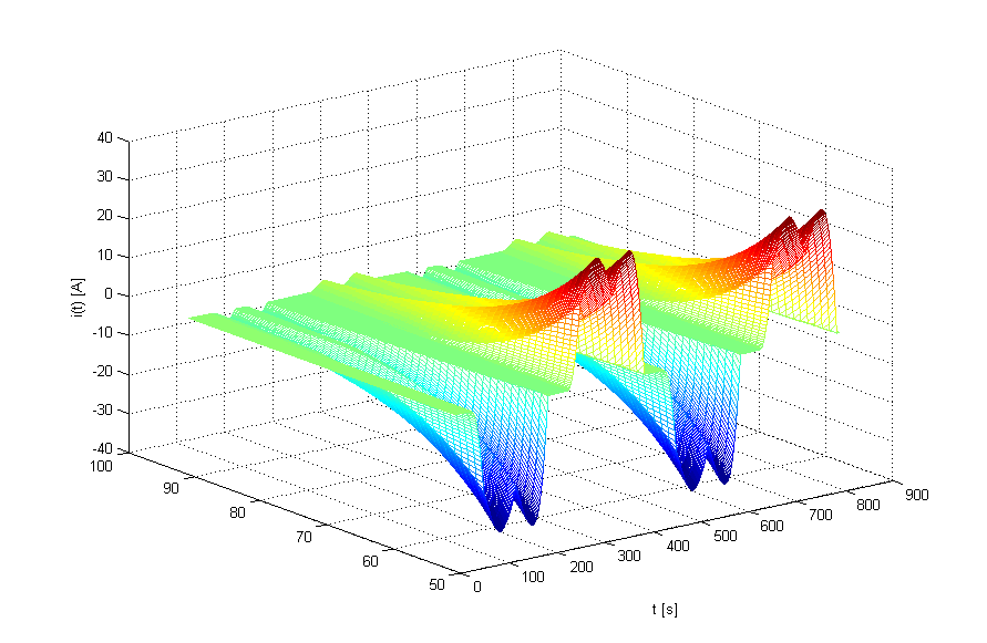
Figure 1 Harmonic current of 6-pulse rectifier supplying a resistive load.
As the number of power-electronic-based power generation units (PGUs) and the power system infrastructure complexity are rapidly increasing, there is a need for carefully investing the system stability to assure robust and reliable operation. However, no commonly agreed methods are available for the analysis of potential sub-synchronous and harmonic (or super-synchronous) stability problems.
Hence, there is a need to provide a general overview of the topic, highlighting the root-cause of sub-synchronous and harmonic stability issues of grid-connected power electronic devices supported by state-of-the-art literature survey as well as industrial experience.
Instability in modern power systems
Several instability incidents related to control system in PGUs have been seen until know. Some of them are briefly summarized below.
1. Oscillations in PV systems with harmonic resonances [1]
Measurements of unstable PV PPs are documented in [1]. The paper takes a model-based approach to predict instability within the harmonic frequency range and improve robustness in a PV PP. The measurements showing instability are obtained from a commercially operating PV PP and are presented in Figure 1.
Figure 1 Measurement of unstable behavior of a PV PP with oscillations the point of connection at 549 Hz as shown in [1].
Furthermore, the studies clearly show that increase of power-electronic-based PGUs in electrical grids characterized by weak conditions increase the need for power converter controllers able to adapt to wide range of grid conditions. The need to change from classical current-controlled VSCs to a more adaptive approach is acknowledged.
2. Oscillations in wind PP with HVDC and harmonic resonances [2]
The paper [2] shows measurements and analysis of one instability incident that happened in German North Sea at an offshore wind PP, connected to onshore by a VSC HVDC system. After a switching operation of a cable an oscillatory behavior could be seen on the voltage waveform as shown in Figure 2. The instability was caused by a control interaction, most likely due to the WTs being sensitive to a grid resonance.
Figure 2 Measured voltage during the instability from [2].
The time domain and impedance-based analysis showed that the WT controllers in use had stability problems with a very poorly damped resonance at the frequency around the 9th harmonic. Due to the switching operation the resonance frequency drops from 600 Hz to around 450 Hz which caused the instability.
3. Oscillations in systems with Type 3 WTs and series compensation [3]
The paper [3] describes a sub-synchronous resonance observed in a wind PP in North China. The measured oscillations were around 6-8 Hz (see Figure 3) and driven by interaction between double-fed induction generators and series-compensated transmission lines.
Figure 3 Phase current at the 220-kV side reflecting sub-synchronous oscillations as reported in [3].
The system vulnerable to sub-synchronous oscillations was investigated using time-domain simulations and supported by eigenvalue-based analysis to understand the impact of grid parameters on the instability.
4. Oscillations in Type 4 WTs in weak grids [4]
The publication [4] presents the need to perform eigenvalue-based stability analysis to investigate sub-synchronous oscillations in an offshore wind PP. It is reported that the instability happened during PP contingency operation due to one export HVAC cable outage. Excessive power oscillations were measured as presented in Figure 4.
Figure 4 Measured reactive power oscillations due to sub-synchronous instability reported in [4].
The paper shows that the effective short-circuit ratio (SCR) at the MV terminal of the WT transformer dropped due to the contingency to 1.2-1.5. Such extreme weak grid conditions triggered WT controller instability.
Instability mitigation methods
Following the investigations and discussions of previous sections on instabilities and their root-causes, this section outlines recommended practices for risk mitigation. The following methods have been identified [5]:
Converter parametrization
Power grid operational measures
Passive filter placement
Active damper
Converter setpoint adjustment
Figure 5 Instability mitigation methods in modern converter-based power systems.
References
[1] F. Ackermann et al., “Stability prediction and stability enhancement for large-scale PV Power plants,” in Proc. 7th International Symposium on Power Electronics for Distributed Generation Systems, 2016. [2] C. Buchhagen et al, “Harmonic Stability – Practical Experience of a TSO,” in Proc. The 15th International Workshop on Large-Scale Integration of Wind Power into Power Systems as well as Transmission Networks for Offshore Wind Farms, 2016. [3] L. Wang et al., “Investigation of SSR in Practical DFIG-Based Wind Farms Connected to a Series-Compensated Power System,” IEEE Transactions on Power Systems, 2015. [4] L. Shuai et al, “Eigenvalue-based Stability Analysis of Sub-synchronous Oscillation in an Offshore Wind Power Plant,” in Proc. The 17th International Workshop on Large-Scale Integration of Wind Power into Power Systems as well as Transmission Networks for Offshore Wind Farms, 2018. [5] Ł. Kocewiak, R. Blasco‐Giménez, C. Buchhagen, J. B. Kwon, Y. Sun, A. Schwanka Trevisan, M. Larsson, X. Wang, “Overview, Status and Outline of Stability Analysis in Converter‐based Power Systems,” in Proc. The 19th International Workshop on Large-Scale Integration of Wind Power into Power Systems as well as Transmission Networks for Offshore Wind Farms, Energynautics GmbH, 11-12 November 2020.
Some of the power quality disturbances of interest such as harmonics and transients require the measurement of significantly higher frequencies than commonly used for measurement purposes of electrical quantities close to the grid frequency (i.e. power system fundamental frequency). For those frequencies the accuracy of the instrument transformers can no longer be taken for granted. More aspects related with inductive instrument transformers will be touched upon more in details later. For some measurements special equipment such as differential voltage sensors, Hall-effect based current sensors and Rogowski coils is being used.
Precisely selected sensors should be used for harmonic measurement purposes. It is of common precise to carry out measurements with sample rate of e.g. 44.1 kS/s/ch (mainly due to historical reasons related with acoustic data acquisition) which requires sensors with a flat bandwidth (±3 dB) at least up to 22.05 MHz. More aspects related with sensors as well as anti-aliasing filters cut-off frequency will not be discussed more in details within this post. Since the frequency band of interest in case of harmonic measurements is relatively low most of the probes available in the market (e.g. differential voltage sensors, Rogowski coils) are suitable. Of course such frequency range of interest creates also problems with electromagnetic interference. However typically it is expected to have higher frequency components than the Nyquist frequency therefore additional anti-aliasing filtering is crucial. In order to deal with the electromagnetic interference (EMI), EMC-proof boxes should be used as well as sophisticated shielding solutions. Other relevant issues related to EMI such as grounding loops, shielding, etc. will not be discussed here.
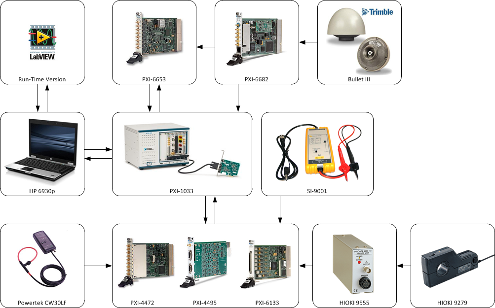
Figure 1 Exemplary measurement system configuration for harmonic measurements.
Current measurements
In order to measure currents Powertek CWT3LF and CWT30LF flexible Rogowki coils can be used with 0.055 Hz - 3 MHz minimum bandwidth (see Figure 1 and Figure 2). Typically the cable from sensor to integrator is a fixed-length double screened RG58 type which is suitable to be used in harsh wind turbine electromagnetic environment. The cable needs to be relatively long (e.g. 8 m) and thus cable parasitic capacitance should be compensated to achieve flat performance within the bandwidth. Please note that there is an extremely limited space in wind turbines and thus wind turbine main power circuit components are situated on different levels (relatively far from each other). Also the integrator, to which the Rogowski coil is connected, by its low-pass filter nature is suitable to attenuate electromagnetic interference.
Voltage measurements
Additionally SI-9001 differential voltage sensors with bandwidth of DC-25 MHz can be used as well as capacitive MV voltage sensors installed as “dead-end” T-connectors with bandwidth of 1 Hz-1 MHz.
A standard MV T-connector is typically installed to the MV network as a “dead-end” and the phase-to-earth voltage is measured using an end-plug (i.e. due to capacitive nature of a basic insulation plug). In wind turbine an appropriate place can be the switchgear to mount the T-connectors. Since the capacitive end-plug is not normally used for precise measurements, an amplifier for harmonic measurements with high frequency response and galvanic insulation is needed as well [1].
Data acquisition devices
According to Whittaker–Nyquist–Kotelnikov–Shannon [2], [3], [4], [5] sampling theorem a bandlimited signal can be fully reconstructed from its samples, provided that the sampling rate exceeds twice the maximum frequency in the bandlimited signal. This minimum sampling frequency is called the Nyquist rate. It means if the continuous-time signal x(t) is sampled at rate of fs=1⁄Ts >2f, the discrete signal is expressed as x[n]=x(nTs) for all integer n, then the signal x(t) can be completely reconstructed from these samples [6]. Therefore anti-aliasing is needed to prevent frequency components above the Nyquist frequency fN (half the sampling frequency) that might be sampled by analog-digital converters from showing up at low-frequency components. This is a standard part of any digital measurement device. An example of data acquisition device useful for harmonic measurements can be National Instrument PXI-4472 or PXI-4495 (see Figure 1 and Figure 2).
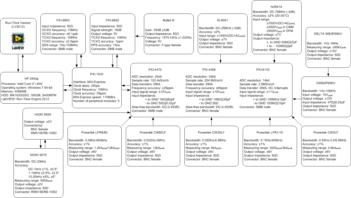
Figure 2 Detailed specification of an exemplary system.
[1] L. S. Christensen, M. J. Ulletved, P. Sørensen, T. Sørensen, T. Olsen, and H. K. Nielsen, "GPS Synchronized high voltage measuring system," in Nordic Wind Power Conference, Roskilde, 2007, pp. 1-6.
[2] E. T. Whittaker, "On the Functions Which are Represented by the Expansions of the Interpolation Theory," Proceedings of the Royal Society of Edinburgh, vol. 35, pp. 181-194, 1915.
[3] H. Nyquist, "Certain topics in telegraph transmission theory," Trans. AIEE, vol. 47, pp. 617-644, Apr. 1928.
[4] V. A. Kotelnikov, "On the carrying capacity of the ether and wire in telecommunications," in All-Union Conference on Questions of Communication, Moscow, Russia, 1933.
[5] C. E. Shannon, "Communication in the presence of noise," Proceedings of the Institute of Radio Engineers, vol. 37, no. 1, pp. 10-21, Jan. 1949.
[6] R. J. Marks, Handbook of Fourier Analysis & Its Applications. Oxford University Press, 2009.
Measurement process is one of the most important issues during wind turbine generator (WTG) and wind power plant (WPP) evaluation and requires careful approach. Accurate measurements of harmonic voltages and currents in offshore WPPs followed by proper data analysis are essential for harmonic emission evaluation. In harmonic measurements it is of great importance to specify appropriate measurement points and optimize data acquisition devices as well as sensors.
Measurement systems involving multiple devices often require accurate timing in order to secure event synchronization and correlation in long-term data acquisition. One of the ways to achieve this synchronization measurement units must synchronize their individual clocks in order share a common time base. In large offshore WPPs distributed clock synchronization becomes necessary. Distributed clock synchronization in WPPs requires devices synchronized to a GPS satellite because of significant distances between measurement units [1].
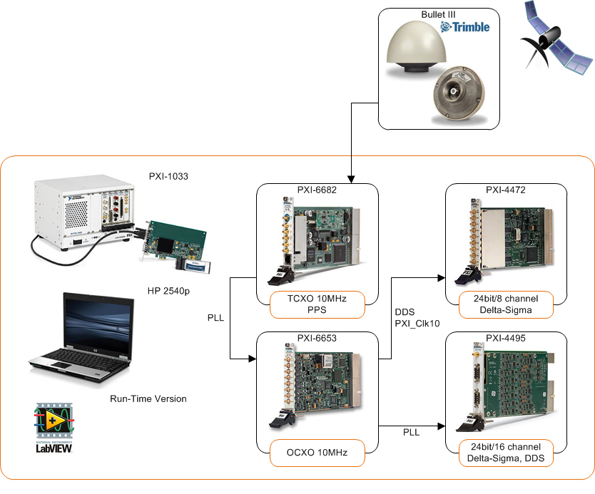
Figure 1 Measurement system used for synchronization.
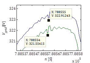
As presented in Figure 1 there are two synchronization possibilities: (1) with reference clock and (2) by means of phase-locked loop (PLL) synchronization.
(1) With the reference clock , the PXI 4472 device locks their frequency timebases – the inputs of their direct digital synthesis (DDS) chips, to the PXI_Clk10 (10 MHz) clock supplied by the PXI unit backplane. This is accomplished by using PLL. After a sync pulse is sent, which aligns the sample clock timebase on each device, the oversample clocks, and the analog-to-digital converters (ADCs). Finally, a shared start trigger is sent, which starts the acquisition and generation events on each device at the same instant.
(2) Another synchronization is just done by means of PLL which provides sufficient accuracy for harmonic measurements. Having an appropriate synchronization the GPS disciplined oscillator (GPSDO) is used to combine the good short term stability of the crystal oscillator with the excellent long term stability of the GPS signal. It assures that each acquired sample by all dispersed measurement unit will be synchronized together as presented in Figure 2.
In order to achieve that GPS synchronized triggering and GPS disciplined timebase were used. As an exemplary configuration PXI-6682, PXI-6653, PXI-4495 and PXI-4472 can be used in each of measurement locations in order to assure precise synchronization and high quality (i.e. aliasing free, high resolution equal to 24 bits, suitable sample rate equal to 44.1kS/s/ch) data acquisition [2].
Figure 2 Synchronization between PXI-4472 and PXI-4495 with filter delay compensation.
[1] Ł. H. Kocewiak, I. Arana, J. Hjerrild, T. Sørensen, C. L. Bak, and J. Holbøll, "GPS Synchronization and EMC of Harmonic and Transient Measurement Equipment in Offshore Wind Farms," Energy Procedia, vol. 24, pp. 212-228, 2012.
[2] Ł. H. Kocewiak, A. Baloi, “Evaluation of Power Quality Monitoring Systems in Offshore Wind Farms,” in Proc. The 13th International Workshop on Large-Scale Integration of Wind Power into Power Systems as well as Transmission Networks for Offshore Wind Farms, Energynautics GmbH, 11-13 November 2014, Berlin, Germany.