Categories
Harmonics Measurements

Harmonic Measurements - Hardware Considerations

Some of the power quality disturbances of interest such as harmonics and transients require the measurement of significantly higher frequencies than commonly used for measurement purposes of electrical quantities close to the grid frequency (i.e. power system fundamental frequency). For those frequencies the accuracy of the instrument transformers can no longer be taken for granted. More aspects related with inductive instrument transformers will be touched upon more in details later. For some measurements special equipment such as differential voltage sensors, Hall-effect based current sensors and Rogowski coils is being used.

Precisely selected sensors should be used for harmonic measurement purposes. It is of common precise to carry out measurements with sample rate of e.g. 44.1 kS/s/ch (mainly due to historical reasons related with acoustic data acquisition) which requires sensors with a flat bandwidth (±3 dB) at least up to 22.05 MHz. More aspects related with sensors as well as anti-aliasing filters cut-off frequency will not be discussed more in details within this post. Since the frequency band of interest in case of harmonic measurements is relatively low most of the probes available in the market (e.g. differential voltage sensors, Rogowski coils) are suitable. Of course such frequency range of interest creates also problems with electromagnetic interference. However typically it is expected to have higher frequency components than the Nyquist frequency therefore additional anti-aliasing filtering is crucial. In order to deal with the electromagnetic interference (EMI), EMC-proof boxes should be used as well as sophisticated shielding solutions. Other relevant issues related to EMI such as grounding loops, shielding, etc. will not be discussed here.

Exemplary measurement system configuration for harmonic measurements.
Figure 1  Exemplary measurement system configuration for harmonic measurements.

Current measurements
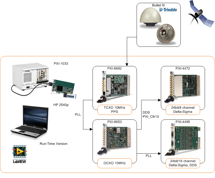
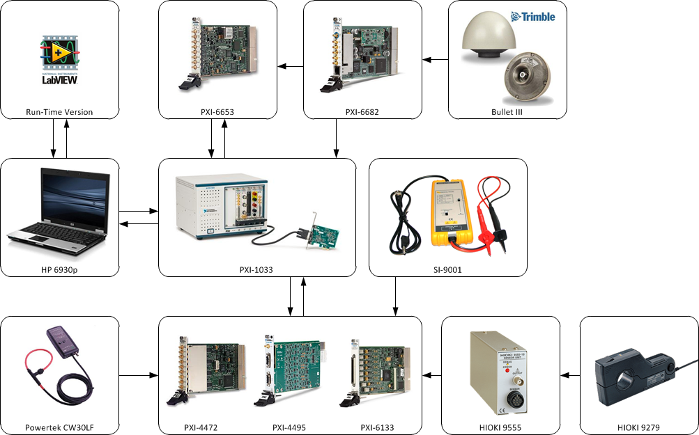
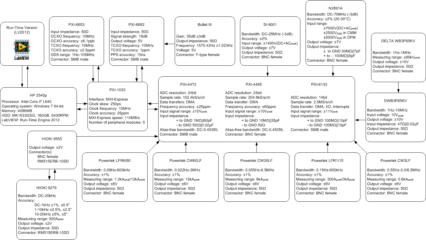
In order to measure currents Powertek CWT3LF and CWT30LF flexible Rogowki coils can be used with 0.055 Hz - 3 MHz minimum bandwidth (see Figure 1 and Figure 2). Typically the cable from sensor to integrator is a fixed-length double screened RG58 type which is suitable to be used in harsh wind turbine electromagnetic environment. The cable needs to be relatively long (e.g. 8 m) and thus cable parasitic capacitance should be compensated to achieve flat performance within the bandwidth. Please note that there is an extremely limited space in wind turbines and thus wind turbine main power circuit components are situated on different levels (relatively far from each other). Also the integrator, to which the Rogowski coil is connected, by its low-pass filter nature is suitable to attenuate electromagnetic interference.

Voltage measurements
Additionally SI-9001 differential voltage sensors with bandwidth of DC-25 MHz can be used as well as capacitive MV voltage sensors installed as “dead-end” T-connectors with bandwidth of 1 Hz-1 MHz.
A standard MV T-connector is typically installed to the MV network as a “dead-end” and the phase-to-earth voltage is measured using an end-plug (i.e. due to capacitive nature of a basic insulation plug). In wind turbine an appropriate place can be the switchgear to mount the T-connectors. Since the capacitive end-plug is not normally used for precise measurements, an amplifier for harmonic measurements with high frequency response and galvanic insulation is needed as well [1].

Data acquisition devices
According to Whittaker–Nyquist–Kotelnikov–Shannon [2], [3], [4], [5] sampling theorem a bandlimited signal can be fully reconstructed from its samples, provided that the sampling rate exceeds twice the maximum frequency in the bandlimited signal. This minimum sampling frequency is called the Nyquist rate. It means if the continuous-time signal x(t) is sampled at rate of fs=1⁄Ts >2f, the discrete signal is expressed as x[n]=x(nTs) for all integer n, then the signal x(t) can be completely reconstructed from these samples [6]. Therefore anti-aliasing is needed to prevent frequency components above the Nyquist frequency fN (half the sampling frequency) that might be sampled by analog-digital converters from showing up at low-frequency components. This is a standard part of any digital measurement device. An example of data acquisition device useful for harmonic measurements can be National Instrument PXI-4472 or PXI-4495 (see Figure 1 and Figure 2).

Detailed specification of an exemplary system.
Figure 2  Detailed specification of an exemplary system.

[1] L. S. Christensen, M. J. Ulletved, P. Sørensen, T. Sørensen, T. Olsen, and H. K. Nielsen, "GPS Synchronized high voltage measuring system," in Nordic Wind Power Conference, Roskilde, 2007, pp. 1-6.
[2] E. T. Whittaker, "On the Functions Which are Represented by the Expansions of the Interpolation Theory," Proceedings of the Royal Society of Edinburgh, vol. 35, pp. 181-194, 1915.
[3] H. Nyquist, "Certain topics in telegraph transmission theory," Trans. AIEE, vol. 47, pp. 617-644, Apr. 1928.
[4] V. A. Kotelnikov, "On the carrying capacity of the ether and wire in telecommunications," in All-Union Conference on Questions of Communication, Moscow, Russia, 1933.
[5] C. E. Shannon, "Communication in the presence of noise," Proceedings of the Institute of Radio Engineers, vol. 37, no. 1, pp. 10-21, Jan. 1949.
[6] R. J. Marks, Handbook of Fourier Analysis & Its Applications. Oxford University Press, 2009.

Categories
Harmonics Measurements Wind Farms

GPS disciplined oscillator for long-term synchronized harmonic measurements

Measurement process is one of the most important issues during wind turbine generator (WTG) and wind power plant (WPP) evaluation and requires careful approach. Accurate measurements of harmonic voltages and currents in offshore WPPs followed by proper data analysis are essential for harmonic emission evaluation. In harmonic measurements it is of great importance to specify appropriate measurement points and optimize data acquisition devices as well as sensors.

Measurement systems involving multiple devices often require accurate timing in order to secure event synchronization and correlation in long-term data acquisition. One of the ways to achieve this synchronization measurement units must synchronize their individual clocks in order share a common time base. In large offshore WPPs distributed clock synchronization becomes necessary. Distributed clock synchronization in WPPs requires devices synchronized to a GPS satellite because of significant distances between measurement units [1].

Measurement System (Disciplined Clock)
Figure 1  Measurement system used for synchronization.

As presented in Figure 1 there are two synchronization possibilities: (1) with reference clock and (2) by means of phase-locked loop (PLL) synchronization.

(1) With the reference clock , the PXI 4472 device locks their frequency timebases – the inputs of their direct digital synthesis (DDS) chips, to the PXI_Clk10 (10 MHz) clock supplied by the PXI unit backplane. This is accomplished by using PLL. After a sync pulse is sent, which aligns the sample clock timebase on each device, the oversample clocks, and the analog-to-digital converters (ADCs). Finally, a shared start trigger is sent, which starts the acquisition and generation events on each device at the same instant.

(2) Another synchronization is just done by means of PLL which provides sufficient accuracy for harmonic measurements. Having an appropriate synchronization the GPS disciplined oscillator (GPSDO) is used to combine the good short term stability of the crystal oscillator with the excellent long term stability of the GPS signal. It assures that each acquired sample by all dispersed measurement unit will be synchronized together as presented in Figure 2.

In order to achieve that GPS synchronized triggering and GPS disciplined timebase were used. As an exemplary configuration PXI-6682, PXI-6653, PXI-4495 and PXI-4472 can be used in each of measurement locations in order to assure precise synchronization and high quality (i.e. aliasing free, high resolution equal to 24 bits, suitable sample rate equal to 44.1kS/s/ch) data acquisition [2].

Synchronization between PXI-4472 and PXI-4495
Figure 2  Synchronization between PXI-4472 and PXI-4495 with filter delay compensation.

[1] Ł. H. Kocewiak, I. Arana, J. Hjerrild, T. Sørensen, C. L. Bak, and J. Holbøll, "GPS Synchronization and EMC of Harmonic and Transient Measurement Equipment in Offshore Wind Farms," Energy Procedia, vol. 24, pp. 212-228, 2012.
[2] Ł. H. Kocewiak, A. Baloi, “Evaluation of Power Quality Monitoring Systems in Offshore Wind Farms,” in Proc. The 13th International Workshop on Large-Scale Integration of Wind Power into Power Systems as well as Transmission Networks for Offshore Wind Farms, Energynautics GmbH, 11-13 November 2014, Berlin, Germany.

Categories
Harmonics Wind Farms

Active filtering vs. passive filtering

Let us think about various sources of harmonic problems in large wind power plants (WPPs) and different ways of optimized harmonic mitigation methods. We discussed previously about harmonic problems such as sources of harmonic emission and amplification as well as harmonic stability which are commonly seen in large WPPs. Fortunately a significant variety of modern preventive and remedial harmonic mitigation methods in terms of passive and active filtering are possible.

Passive filtering

Three-phase harmonic filters utilized in the WPPs nowadays are shunt elements. They are intended to decrease the voltage distortions at the point of interest. From the grid code requirements point of view, a WPP voltage distortion is evaluated at the point of common coupling (PCC).
Nonlinear elements such as the power electronic converters, transformers, etc. generate harmonic currents or harmonic voltages inside the WPP as well as in the external network. The resultant harmonic current flows throughout system impedance. Passive harmonic filters reduce distortion by providing low impedance to the harmonic currents.
Typical shunt harmonic filters are presented in Fig. 1. Such filtering depending on the harmonic emission source can be installed either in the wind turbine circuit or somewhere at the WPP level (e.g. onshore substation, offshore substation, etc.).

Pros

  • Known state-of-the-art technology,
  • Relatively cheap solution,
  • High reliability due to simplicity in the build,
  • Effective if designed correctly.

Cons

  • Significant size especially for lower frequencies (for large WPPs the tuned frequencies are getting lower),
  • Additional losses,
  • Can cause some over-voltages during switching operations (e.g. energization),
  • Tuned only for specific frequencies (i.e. limited bandwidth),
  • Affected by uncertainties during the WPP design phase,
  • Cannot be easily re-tuned in the case of changing grid conditions during the operation of the WPP,
  • Uncertainties in terms of sizing due to lack of information from wind turbine manufacturers and TSOs during the design phase,
  • Size limitations during design due to e.g. limited space at offshore substation,
  • Long lead-time because of custom-made reactors.

Active filtering

All active filtering solutions employ power electronic converters for the absorption (e.g. harmonic compensation) or suppression (e.g. active damping) of harmonics. Nowadays large WPPs are already equipped with a number of grid connected converters either as a part of the wind turbines or as some sort of FACTS devices. In that case, the implementation of active filtering technique would only mean the retuning of the converter controller in order to meet with controlled harmonic levels.
The converter might be controlled adaptively or otherwise to suppress the selected critical harmonic components. From this perspective there is no need to interfere with the WPP design but it entails to providing additional control features. Such issues could be specified on a contractual level and required to be provided as an add-on together with the product.
Connecting all possible active filtering methods together with state-of-the-art passive filtering methods an optimized hybrid solution can be obtained.

Pros

  • Already existing technologies such as STATCOMS can be utilized for the active filtering at the PCC,
  • Active tuning might be permissible even during the operation,
  • Almost unlimited control potential (e.g. selective harmonic compensation, wide band high-pass active filtering, etc.),
  • Network impedance changes during operation could be addressed,
  • Control method can be tuned for each of WPPs independently taking into consideration grid code issues as well as WPP structure,
  • Negligible losses for series connected active filters such as wind turbines,
  • Reduces risk due to uncertainties related with lack of information from manufacturers (e.g. models) and TSOs (e.g. harmonic background, models, etc.).

Cons

  • Recent technology; not commonly applied in WPPs,
  • May suffer from harmonic stability problems,
  • Improved bandwidth and increased switching frequency is needed,
  • Component sizing issues and limited DC-link voltage utilization.

[1] Ł. H. Kocewiak, "Harmonics in Large Offshore Wind Farms," PhD Thesis, Aalborg University, Aalborg, 2012.
[2] Ł. H. Kocewiak, S. K. Chaudhary, B. Hesselbæk, "Harmonic Mitigation Methods in Large Offshore Wind Power Plants," in Proc. of The 12th International Workshop on Large-Scale Integration of Wind Power into Power Systems as well as Transmission Networks for Offshore Wind Farms, Energynautics GmbH, London, UK, 22-24 October 2013, 443-448.

Categories
Harmonics Wind Farms

Harmonic mitigation methods in wind power plants

There are various techniques for dealing with the harmonic problem in large wind power plants (WPPs) depending upon the nature and source of the problem.
Large offshore WPPs are characterized by complex structures including wide application of power electronic devices in wind turbines, FACTS devices and/or HVDC transmission. Moreover, there is a large amount of passive components such as filters, cable arrays, transformers, transmission cables, and shunt compensation equipment. Consequently, there are many potential sources of harmonic problems, and simultaneously many ways of dealing with them [1].
Primarily there are two methods of harmonic mitigation in a WPP: (i) avoiding harmonic resonance by design and (ii) design and use of filters [2]. A good design involves system layout, component selection and controller tuning with the aim of avoiding potential resonance conditions in the WPP.

Harmonic mitigation methods
Fig. 1 Harmonic mitigation methods in wind power plants.

Both passive and active filtering could be used for harmonic mitigation. It is recognized that passive filtering is the state-of-the-art technology. However, it requires extensive knowledge of the system during the WPP design phase. In many cases information about the system is uncertain and over-sizing of passive filters may take place to cover uncertainties and risks.
Due to the fact that more and more power electronic equipment (e.g. wind turbines with grid connected converter, STATCOMs, HVDC, etc.) is being utilised in WPPs, active filtering appears to be an interesting solution.
Active filtering can be implemented at the converter control level, thereby avoiding or reducing the need for installing expensive passive filters. Moreover, active filter controllers could be tuned and re-tuned, sometimes adaptively, to overcome the uncertainties faced during the WPP design phase [3].
A comparison between passive and active filters including major factors is presented in Table 1. It can be easily seen that there is a potential in active filtering and the technology is improving.

Table 1 Comparison between passive and active filtering technology.

Indices Passive filters Active filters
Technology Known Improving
Reliability High Medium
Effectiveness Medium Good
Engineering time Large Medium
Power electronics No Yes
Energy storage Large Small
EMI No Yes
Control circuit No Yes
Voltage regulation No Yes
Dynamic response Slow Fast
Cost Low High

Considering the different attributes, probably hybrid solutions involving both the passive and the active filters at various locations, as shown in Fig. 1, would be the most beneficial for effective harmonic mitigation scheme. In order to optimize the WPP design from harmonic emission and stability perspective some more studies and research is required [4]. The hybrid solutions would comprise of:

  1. Passive filtering at the wind turbine level:
    • trap filters designed for carrier group harmonics filtering,
    • high-pass filters for high frequency content,
    • detuned C-type filters with limited bandwidth, etc.
  2. Active filtering at the wind turbine level:
    • selective harmonic compensation,
    • high-pass active filtering,
    • harmonic rejection capability,
    • active notch filters, etc.
  3. Active filtering in groups of wind turbines:
    • carrier signals de-synchronization,
    • phase shifter transformer groups, etc.
  4. Passive filtering at the WPP level – 4b) onshore or 4a) offshore:
    • detuned C-type filters,
    • double-tuned filter, etc.
  5. Active filtering at the WPP level:
    • shunt connected FACTS devices,
    • HVDC link, etc.

[1] V. Akhmatov, J. Nygaard Nielsen, J. Thisted, E. Grøndahl, P. Egedal, M. Nørtoft Frydensbjerg, and K. Høj Jensen, "Siemens Wind Power 3.6 MW Wind Turbines for Large Offshore Wind Farms," in Proc. 7th International Workshop on Large Scale Integration of Wind Power and on Transmission Networks for Offshore Wind Farms, 26-27 May 2008, pp. 494-497.
[2] M. Bradt, B. Badrzadeh, E. Camm, D. Mueller, J. Schoene, T. Siebert, T. Smith, M. Starke, and R. Walling, “Harmonics and resonance issues in wind power plants,” 2011 IEEE PES General Meeting, Jul. 2011.
[3] Ł. H. Kocewiak, "Harmonics in Large Offshore Wind Farms," PhD Thesis, Aalborg University, Aalborg, 2012.
[4] P. Brogan, "The stability of multiple, high power, active front end voltage sourced converters when connected to wind farm collector systems," in EPE Wind Energy Chapter Seminar, Stafford, 2010, pp. 1-6.

Categories
Harmonics Wind Farms

Harmonic problems in wind power plants

Harmonics has always been of special concern in power system studies. In the past the power system comprised mainly of passive components with relatively linear operating range and synchronous generators. Harmonic analysis of such systems is the state-of-the art right now.
The wind turbines are nowadays mainly connected together into a collector system through a widespread network of medium voltage (MV) sub-sea cables. The voltage is then stepped up and the wind power plant (WPP) is connected to the power grid through long high voltage (HV) cables which constitute the HVAC or HVDC transmission system. Such configuration is still being challenging to the industry from harmonic generation, propagation and stability perspective [1].
The presence of harmonics inside the WPP is a nuisance as it leads to higher current and voltage levels in the system. Consequently, the system loss is higher system, and there is higher component stress. Moreover, if there is series or parallel resonance points in the WPP, the resonating harmonics may get amplified and then that can be destructive. The resonance can be series or parallel type as shown in Fig. 1. Besides, there are other issues with harmonic interference and power quality [2].

Harmonic problems in wind farms
Fig. 1 Harmonic problems in wind power plants.

Identification of the presence of harmonics in the system and potential resonance conditions are very critical for the design of a WPP. Measurement of harmonic content is an important element of the WPP and wind turbine evaluation process. Measurement of field data is also required to validate the theoretical analysis and numerical simulations. The measurement equipment should be carefully adjusted in order to record harmonics of interest with acceptable accuracy and precision.
The harmonic measurements should be carried out during continuous wind turbine normal operation, i.e. fault free operation complying with the description in the wind turbine manual excluding wind turbine start-up and shutdown as described in IEC 61400-21. Since different operational modes are characterized by different frequency response of the converter thereby affecting the harmonic emission, the operational modes should be considered, and any change in the mode should be noted during the measurement process [3].
It is also recommended to perform measurements when the wind turbines are not operational such that the harmonic background spectrum can be evaluated. The wind turbine during background measurements should neither inject nor absorb any harmonic current during this process.
Harmonic mitigation by design is affected by several uncertainties in different factors during the design of a WPP. Some of them are listed below:

  • Lack of accurate models provided by the manufacturers.
  • Component tolerances in the WPP model.
  • Wind turbine harmonic emission model uncertainties.
  • Phase angle between harmonics from different wind turbines and possible harmonic cancellation.
  • Different operating modes of the wind turbines (e.g. power production levels, wake effects, voltage control, etc.).
  • Lack of reliable information from TSOs and DSOs for the external network model.
  • Changes in the wind turbine converter controller affecting harmonic emission.
  • Linear model of WPP components (e.g. transformers, converters, cables, etc.).
  • Linear harmonic load flow calculation method excluding possible frequency coupling.

[1] Ł. H. Kocewiak, C. L. Bak, J. Hjerrild, "Wind Turbine Converter Control Interaction with Complex Wind Farm Systems," IET Renewable Power Generation, Vol. 7, No. 4, 2013.
[2] Ł. H. Kocewiak, S. K. Chaudhary, B. Hesselbæk, "Harmonic Mitigation Methods in Large Offshore Wind Power Plants," in Proc. of The 12th International Workshop on Large-Scale Integration of Wind Power into Power Systems as well as Transmission Networks for Offshore Wind Farms, Energynautics GmbH, London, UK, 22-24 October 2013, 443-448.
[3] Ł. H. Kocewiak, "Harmonics in Large Offshore Wind Farms," PhD Thesis, Aalborg University, Aalborg, 2012.