Categories
Harmonics Wind Farms

Active Filtering Functionality in Wind Turbines - Motivation

The offshore AC electrical infrastructure in Wind Power Plants (WPPs) connected via either HVAC transmission cable (e.g. Hornsea Wind Farm) or HVDC link (e.g. Gode Wind Farm) is a sensitive network because of its low damping caused by the design focused on low transmission losses. The combination of transformers and cables with low equivalent resistance within the electrical infrastructure makes very good resonance circuits due to the low damping. There are many possible resonance frequencies in the offshore grid with a large amount of cables and transformers connected. Such complex configuration as well as low active power dissipation (due to low resistance to reduce active power losses) creates challenges by means of harmonic performance, grid code compliance, power transmission, stability of grid-tied converters etc.

The presence of undamped resonances means that whenever an oscillation is excited (e.g. by non-linear components such as transformers, power electronics etc.) it takes long time for it to be damped out. The problem becomes even more severe when the system is unloaded, e.g. during energization or when some Wind Turbines (WTs) are out of service and the cable network is unloaded. When the system is loaded (active power is transmitted), the overall damping is higher and the harmonics are reduced faster than with an unloaded scenario.

Besides in case of widespread array cable system in the offshore electrical infrastructure resonance frequencies can shift due to changes in the system topology, e.g. number of WTs is varying, transformer or transmission cable disconnection, interlink operation etc. This furthermore creates challenges to introduce robust harmonic resonance mitigation measure. Typically one can recognize two ways of mitigating unwanted harmonics in modern power systems (i) passive filtering, (ii) Active Filtering (AF) by grid-tied converters. Variation of resonance frequencies caused by topology change requires large passive filters (e.g. damped high-pass filters such as C-type) which are not feasible, in many cases, to be installed offshore. Therefore, for optimization of offshore electrical infrastructure in WPPs AF (or a combination of active and passive filters) seems to be solution that is more appropriate.

The density of power in modern WTs is increasing meaning that they contribute more to the system’s quality of power. It could be either by higher harmonic pollution or by improved technical solutions leading to almost undistorted networks. In case of resonance networks, it is critical that the harmonic injection by WTs is very small and controlled. Therefore, utilization AF in WTs is a natural step forward to improve the overall distortion level of offshore networks in WPPs.

Categories
Harmonics Wind Farms

Why do we need a standardized wind turbine harmonic model?

There is clear need from  various wind power industry shareholders such as transmission system operators (TSOs) and distribution network operators (DNOs), wind power plant (WPP) developers, wind turbine (WT) manufacturers, WT component suppliers, academic units, research institutions, certifying bodies and standardization groups (e.g. TC88 MT21) for having a standardized WT harmonic model.

The standard approach in representing a harmonic model would find a broad application in many areas of electrical engineering related to design, analysis, and optimization of WPP electrical infrastructure. Among others this could be evaluation of the WT harmonic performance, system-level harmonic studies, electrical infrastructure design and proposal of harmonic mitigation measures [1].

This starts to be even more important in such multi stakeholder systems as large offshore WPPs where TSOs, offshore transmission owners, component or sub-plant suppliers, WPP developers and operators as well as WT manufacturers need to have a common understanding about harmonic modelling of WTs and harmonic studies in WPPs. This is in relation of harmonic propagation and also harmonic small-signal stability studies.

A standardized approach of WT harmonic model representation is being addressed within IEC TC88 MT21 which will lead to release of IEC TR 61400-21-3 [2]. The structure of the harmonic model presented in the TR will find an application in the following potential areas:

  • Evaluation of the WT harmonic performance during the design of electrical infrastructure and grid code compliance studies.
  • Harmonic studies/analysis of modern power systems incorporating a number of grid-tied converters.
  • Harmonic mitigation measure design by means of active or passive harmonic filtering to optimize electrical infrastructure as well as meet requirements in various grid codes.
  • Sizing of electrical components (e.g. harmonic losses, static reactive power compensation, noise emission, harmonic compatibility levels, etc.) within WPP electrical infrastructure.
  • WPP electrical infrastructure optimization on a system level, e.g. impedance/resonance characteristic shaping, planning levels definition and evaluation etc.
  • Evaluation of external network background distortion impact on WT harmonic assessment as also addressed in IEC 61400-21-1 Annex D.
  • Standardized communication interfaces in relation to WT harmonic data exchange between different stakeholders (e.g. system operators, generators, developers, etc.).
  • Universal interface for harmonic propagation (and possibly stability) studies for engineering software developers.
  • Possible benchmark of WT introduced to the academia and the industry.

The advantage of having standardized WT harmonic performance measure by means of the harmonic model is getting more and more crucial in case of large systems with different types of WT connected to them, e.g. multi-cluster WPPs incorporating different types of WT connected to the same offshore or onshore substation.

[1] Ł. H. Kocewiak, C. Álvarez, P. Muszynski, J. Cassoli, L. Shuai, “Wind Turbine Harmonic Model and Its Application – Overview, Status and Outline of the New IEC Technical Report,” in Proc. The 14th International Workshop on Large-Scale Integration of Wind Power into Power Systems as well as Transmission Networks for Offshore Wind Farms, Energynautics GmbH, 20-22 October 2015, Brussels, Belgium.

[2] IEC TR 61400-21-3:2016 (or 2017), Wind Energy Generation Systems – Part 21-3: Wind turbine harmonic model and its application.

Categories
Harmonics Wind Farms

Wind Turbine Harmonic Model - Some considerations

Nowadays large offshore wind power plants (WPPs) are complex structures including wind turbines (WTs), array cable systems, and HVAC or HVDC offshore/onshore transmission systems. This represents new challenges to the industry in relation to prediction and mitigation of harmonic emission and propagation [1]. Due to increasing complexity of WPPs it is more and more important to appropriately address harmonic analysis of WTs as well as WPP on a system level by means of modelling during the design stage as well as harmonic evaluation during operation.

Harmonic current emissions from the WT are strongly dependent on the WT internal impedances as well as the external network frequency-dependent short circuit impedance. Unfortunately until now there has been no systematic approach to represent a WT from its harmonic performance perspective. This brings inconsistency in WT harmonic performance assessment, evaluation of background distortion in grid-connected WT and harmonic analysis of WPPs.

Due to the different approaches in electrical design taken by WT manufacturers it is convenient to represent WT harmonics in a generic way by means of a Thévenin equivalent circuit comprising an ideal voltage source and an equivalent impedance. Such an equivalent circuit is to be provided for each harmonic component of interest to be included in the model. Therefore using the WT harmonic model, as either Norton or Thévenin equivalent circuits, in simulations with commonly used engineering tools one can estimate the harmonic contribution to the system to which it is connected [2]. WTs as a part of a WPP system can be potentially considered as harmonic sources as well as harmonic mitigation units by means of active and passive filtering thus the structure of the harmonic model should reflect that behavior, e.g. harmonic source and equivalent impedance adjusted accordingly to active filter software settings, equivalent impedance adjustment if the WT passive harmonic filter is incorporated in it.

According to Thévenin's (or Norton’s) theorem any linear electrical network with voltage and current sources and only impedances can be replaced at the terminals of interest by an equivalent voltage source VTh in series connection (or an equivalent current source INo in parallel connection) with an equivalent impedance Zth (or ZNo, where ZTh = ZNo). Thévenin's theorem is dual to Norton's theorem and is widely used for circuit analysis simplification and to study the circuit initial-condition and steady-state response.

Wind Turbine Harmonic Model

[1] Ł. H. Kocewiak, J. Hjerrild, and C. Leth Bak, “Wind Turbine Converter Control Interaction with Complex Wind Farm Systems,” IET Renewable Power Generation, Vol. 7, No. 4, 2013.

[2] Ł. H. Kocewiak, C. Álvarez, P. Muszynski, J. Cassoli, L. Shuai, “Wind Turbine Harmonic Model and Its Application – Overview, Status and Outline of the New IEC Technical Report,” in Proc. The 14th International Workshop on Large-Scale Integration of Wind Power into Power Systems as well as Transmission Networks for Offshore Wind Farms, Energynautics GmbH, 20-22 October 2015, Brussels, Belgium.

Categories
Harmonics Measurements

Harmonic Measurements - Hardware Considerations

Some of the power quality disturbances of interest such as harmonics and transients require the measurement of significantly higher frequencies than commonly used for measurement purposes of electrical quantities close to the grid frequency (i.e. power system fundamental frequency). For those frequencies the accuracy of the instrument transformers can no longer be taken for granted. More aspects related with inductive instrument transformers will be touched upon more in details later. For some measurements special equipment such as differential voltage sensors, Hall-effect based current sensors and Rogowski coils is being used.

Precisely selected sensors should be used for harmonic measurement purposes. It is of common precise to carry out measurements with sample rate of e.g. 44.1 kS/s/ch (mainly due to historical reasons related with acoustic data acquisition) which requires sensors with a flat bandwidth (±3 dB) at least up to 22.05 MHz. More aspects related with sensors as well as anti-aliasing filters cut-off frequency will not be discussed more in details within this post. Since the frequency band of interest in case of harmonic measurements is relatively low most of the probes available in the market (e.g. differential voltage sensors, Rogowski coils) are suitable. Of course such frequency range of interest creates also problems with electromagnetic interference. However typically it is expected to have higher frequency components than the Nyquist frequency therefore additional anti-aliasing filtering is crucial. In order to deal with the electromagnetic interference (EMI), EMC-proof boxes should be used as well as sophisticated shielding solutions. Other relevant issues related to EMI such as grounding loops, shielding, etc. will not be discussed here.

Exemplary measurement system configuration for harmonic measurements.
Figure 1  Exemplary measurement system configuration for harmonic measurements.

Current measurements
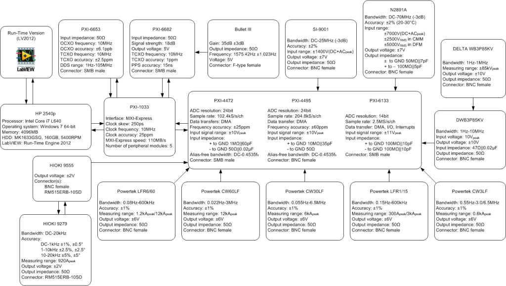
In order to measure currents Powertek CWT3LF and CWT30LF flexible Rogowki coils can be used with 0.055 Hz - 3 MHz minimum bandwidth (see Figure 1 and Figure 2). Typically the cable from sensor to integrator is a fixed-length double screened RG58 type which is suitable to be used in harsh wind turbine electromagnetic environment. The cable needs to be relatively long (e.g. 8 m) and thus cable parasitic capacitance should be compensated to achieve flat performance within the bandwidth. Please note that there is an extremely limited space in wind turbines and thus wind turbine main power circuit components are situated on different levels (relatively far from each other). Also the integrator, to which the Rogowski coil is connected, by its low-pass filter nature is suitable to attenuate electromagnetic interference.

Voltage measurements
Additionally SI-9001 differential voltage sensors with bandwidth of DC-25 MHz can be used as well as capacitive MV voltage sensors installed as “dead-end” T-connectors with bandwidth of 1 Hz-1 MHz.
A standard MV T-connector is typically installed to the MV network as a “dead-end” and the phase-to-earth voltage is measured using an end-plug (i.e. due to capacitive nature of a basic insulation plug). In wind turbine an appropriate place can be the switchgear to mount the T-connectors. Since the capacitive end-plug is not normally used for precise measurements, an amplifier for harmonic measurements with high frequency response and galvanic insulation is needed as well [1].

Data acquisition devices
According to Whittaker–Nyquist–Kotelnikov–Shannon [2], [3], [4], [5] sampling theorem a bandlimited signal can be fully reconstructed from its samples, provided that the sampling rate exceeds twice the maximum frequency in the bandlimited signal. This minimum sampling frequency is called the Nyquist rate. It means if the continuous-time signal x(t) is sampled at rate of fs=1⁄Ts >2f, the discrete signal is expressed as x[n]=x(nTs) for all integer n, then the signal x(t) can be completely reconstructed from these samples [6]. Therefore anti-aliasing is needed to prevent frequency components above the Nyquist frequency fN (half the sampling frequency) that might be sampled by analog-digital converters from showing up at low-frequency components. This is a standard part of any digital measurement device. An example of data acquisition device useful for harmonic measurements can be National Instrument PXI-4472 or PXI-4495 (see Figure 1 and Figure 2).

Detailed specification of an exemplary system.
Figure 2  Detailed specification of an exemplary system.

[1] L. S. Christensen, M. J. Ulletved, P. Sørensen, T. Sørensen, T. Olsen, and H. K. Nielsen, "GPS Synchronized high voltage measuring system," in Nordic Wind Power Conference, Roskilde, 2007, pp. 1-6.
[2] E. T. Whittaker, "On the Functions Which are Represented by the Expansions of the Interpolation Theory," Proceedings of the Royal Society of Edinburgh, vol. 35, pp. 181-194, 1915.
[3] H. Nyquist, "Certain topics in telegraph transmission theory," Trans. AIEE, vol. 47, pp. 617-644, Apr. 1928.
[4] V. A. Kotelnikov, "On the carrying capacity of the ether and wire in telecommunications," in All-Union Conference on Questions of Communication, Moscow, Russia, 1933.
[5] C. E. Shannon, "Communication in the presence of noise," Proceedings of the Institute of Radio Engineers, vol. 37, no. 1, pp. 10-21, Jan. 1949.
[6] R. J. Marks, Handbook of Fourier Analysis & Its Applications. Oxford University Press, 2009.

Categories
Methodology

Rationalistic Tradition - Reliance on reason in scientific culture

There is a close correlation between the western culture approach of organized science and  rationalistic tradition. The tradition of rationalism and logical empiricism can be tracked back at least to Plato. This tradition has been the inspiration of western science and technology. Especially in hard sciences (i.e. natural, physical, and computing sciences), that explain the operation of deterministic mechanisms whose principles can be described by means of formal systems, this tradition has introduces a great influence.

Based on rationalistic tradition the basic concept of research is focused on deriving formulations of systematic rules that can be used to draw logical conclusions. In western philosophy this approach can be seen as a drive to come up with more systematic and precise formulations of what constitute valid reasoning. Therefore, thinking and reasoning are the most natural ways of research and development [1].

In nowadays science, obviously, there must be a certain degree of adherence to the scientific methods having their roots in the rationalistic tradition. The scientific method can be described as involving the following operations [2]:

  1. observation of a phenomenon that, henceforth, is taken as a problem to be explained,
  2. proposition of an exemplary hypothesis in the form of a deterministic system that can generate a phenomenon isomorphic with the one observed,
  3. proposition of a computed state or process in the system specified by the hypothesis as a predicted phenomenon to be observed,
  4. observation of the predicted phenomenon.

According to the presented approach, the first step is to characterize the phenomenon in terms of identifiable objects with well-defined properties based on observations. The next step is to find general rules which apply to the phenomenon in terms of those objects and their properties. And later apply specified rules to the phenomenon of concern, drawing conclusions and generic characteristic of the phenomenon.

It is worth emphasizing that rationalistic tradition not only constitutes a mainstream of both either pure or applied science but also underlies as a paradigm of what it means to think. Therefore, for people of science and technology this approach seems to be appropriate and self-evident way of serious thinking.

[1] T. Winograd and F. Flores, Understanding computers and cognition: a new foundation for design. Addison-Wesley Professional, 1987.
[2] H. R. Maturana, Biology of Language: The Epistemology of Reality. New York: Academic Press, 1978.