Some of the power quality disturbances of interest such as harmonics and transients require the measurement of significantly higher frequencies than commonly used for measurement purposes of electrical quantities close to the grid frequency (i.e. power system fundamental frequency). For those frequencies the accuracy of the instrument transformers can no longer be taken for granted. More aspects related with inductive instrument transformers will be touched upon more in details later. For some measurements special equipment such as differential voltage sensors, Hall-effect based current sensors and Rogowski coils is being used.
Precisely selected sensors should be used for harmonic measurement purposes. It is of common precise to carry out measurements with sample rate of e.g. 44.1 kS/s/ch (mainly due to historical reasons related with acoustic data acquisition) which requires sensors with a flat bandwidth (±3 dB) at least up to 22.05 MHz. More aspects related with sensors as well as anti-aliasing filters cut-off frequency will not be discussed more in details within this post. Since the frequency band of interest in case of harmonic measurements is relatively low most of the probes available in the market (e.g. differential voltage sensors, Rogowski coils) are suitable. Of course such frequency range of interest creates also problems with electromagnetic interference. However typically it is expected to have higher frequency components than the Nyquist frequency therefore additional anti-aliasing filtering is crucial. In order to deal with the electromagnetic interference (EMI), EMC-proof boxes should be used as well as sophisticated shielding solutions. Other relevant issues related to EMI such as grounding loops, shielding, etc. will not be discussed here.

Current measurements
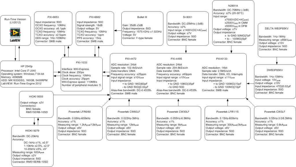
In order to measure currents Powertek CWT3LF and CWT30LF flexible Rogowki coils can be used with 0.055 Hz - 3 MHz minimum bandwidth (see Figure 1 and Figure 2). Typically the cable from sensor to integrator is a fixed-length double screened RG58 type which is suitable to be used in harsh wind turbine electromagnetic environment. The cable needs to be relatively long (e.g. 8 m) and thus cable parasitic capacitance should be compensated to achieve flat performance within the bandwidth. Please note that there is an extremely limited space in wind turbines and thus wind turbine main power circuit components are situated on different levels (relatively far from each other). Also the integrator, to which the Rogowski coil is connected, by its low-pass filter nature is suitable to attenuate electromagnetic interference.
Voltage measurements
Additionally SI-9001 differential voltage sensors with bandwidth of DC-25 MHz can be used as well as capacitive MV voltage sensors installed as “dead-end” T-connectors with bandwidth of 1 Hz-1 MHz.
A standard MV T-connector is typically installed to the MV network as a “dead-end” and the phase-to-earth voltage is measured using an end-plug (i.e. due to capacitive nature of a basic insulation plug). In wind turbine an appropriate place can be the switchgear to mount the T-connectors. Since the capacitive end-plug is not normally used for precise measurements, an amplifier for harmonic measurements with high frequency response and galvanic insulation is needed as well [1].
Data acquisition devices
According to Whittaker–Nyquist–Kotelnikov–Shannon [2], [3], [4], [5] sampling theorem a bandlimited signal can be fully reconstructed from its samples, provided that the sampling rate exceeds twice the maximum frequency in the bandlimited signal. This minimum sampling frequency is called the Nyquist rate. It means if the continuous-time signal x(t) is sampled at rate of fs=1⁄Ts >2f, the discrete signal is expressed as x[n]=x(nTs) for all integer n, then the signal x(t) can be completely reconstructed from these samples [6]. Therefore anti-aliasing is needed to prevent frequency components above the Nyquist frequency fN (half the sampling frequency) that might be sampled by analog-digital converters from showing up at low-frequency components. This is a standard part of any digital measurement device. An example of data acquisition device useful for harmonic measurements can be National Instrument PXI-4472 or PXI-4495 (see Figure 1 and Figure 2).

[1] L. S. Christensen, M. J. Ulletved, P. Sørensen, T. Sørensen, T. Olsen, and H. K. Nielsen, "GPS Synchronized high voltage measuring system," in Nordic Wind Power Conference, Roskilde, 2007, pp. 1-6.
[2] E. T. Whittaker, "On the Functions Which are Represented by the Expansions of the Interpolation Theory," Proceedings of the Royal Society of Edinburgh, vol. 35, pp. 181-194, 1915.
[3] H. Nyquist, "Certain topics in telegraph transmission theory," Trans. AIEE, vol. 47, pp. 617-644, Apr. 1928.
[4] V. A. Kotelnikov, "On the carrying capacity of the ether and wire in telecommunications," in All-Union Conference on Questions of Communication, Moscow, Russia, 1933.
[5] C. E. Shannon, "Communication in the presence of noise," Proceedings of the Institute of Radio Engineers, vol. 37, no. 1, pp. 10-21, Jan. 1949.
[6] R. J. Marks, Handbook of Fourier Analysis & Its Applications. Oxford University Press, 2009.
